Thermal energy storage and cooling system with gravity fed secondary refrigerant isolation

a technology of energy storage and secondary refrigerant isolation, which is applied in the field of cooling systems, can solve the problems of limited success of current air conditioning units having energy storage systems and difficulty in achieving high-efficiency

Active Publication Date: 2008-09-09
ACP THULE INVESTMENTS LLC +1
View PDF59 Cites 31 Cited by
  • Summary
  • Abstract
  • Description
  • Claims
  • Application Information

AI Technical Summary

Problems solved by technology

Current air conditioning units having energy storage systems have had limited success due to several deficiencies including reliance on water chillers that are practical only in large commercial buildings and have difficulty achieving high-efficiency.

Method used


Image

  • Thermal energy storage and cooling system with gravity fed secondary refrigerant isolation
  • Thermal energy storage and cooling system with gravity fed secondary refrigerant isolation
  • Thermal energy storage and cooling system with gravity fed secondary refrigerant isolation

Examples


Embodiment Construction

[0020]While this invention is susceptible to embodiment in many different forms, there is shown in the drawings and will be described herein in detail specific embodiments thereof with the understanding that the present disclosure is to be considered as an exemplification of the principles of the invention and is not to be limited to the specific embodiments described.

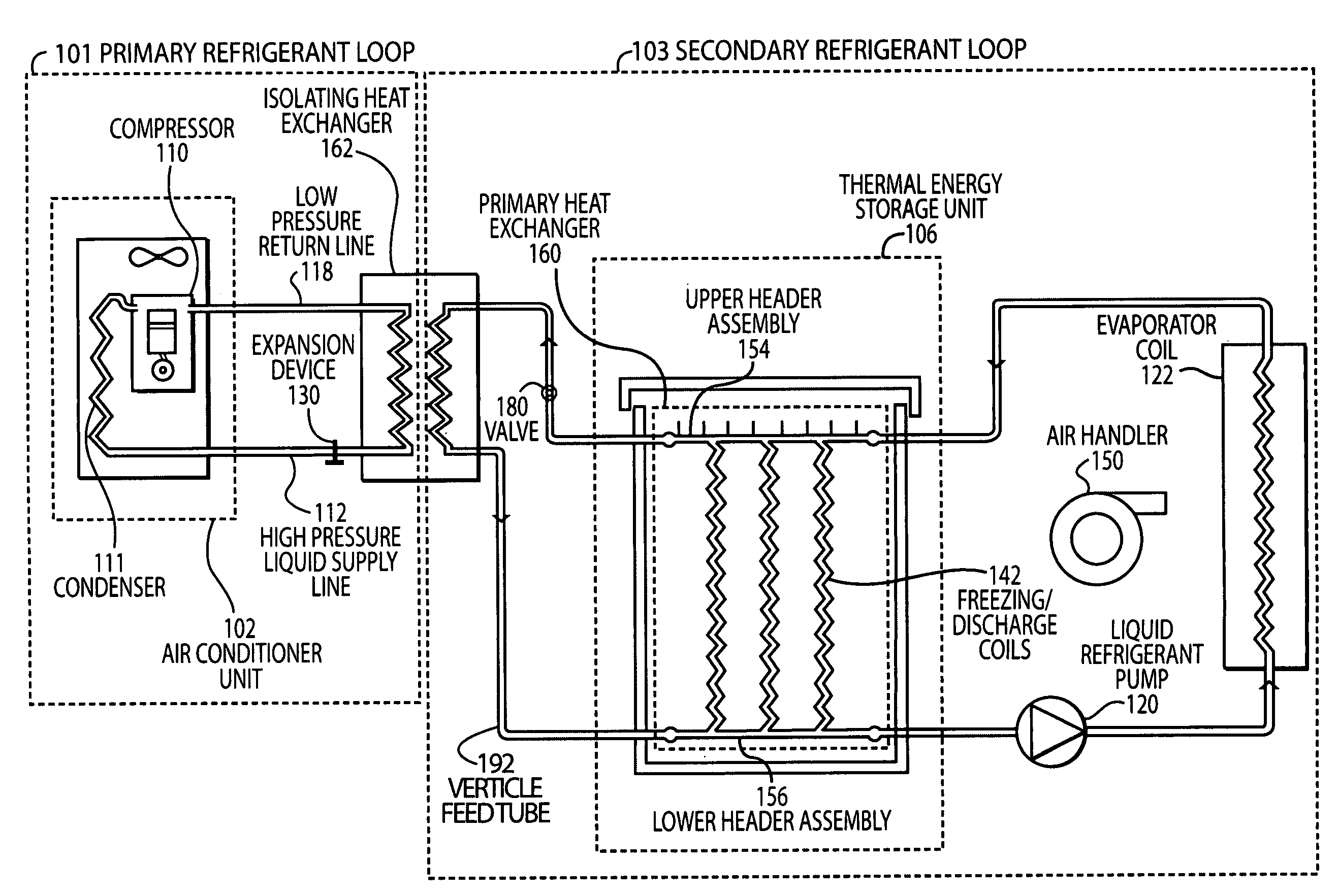
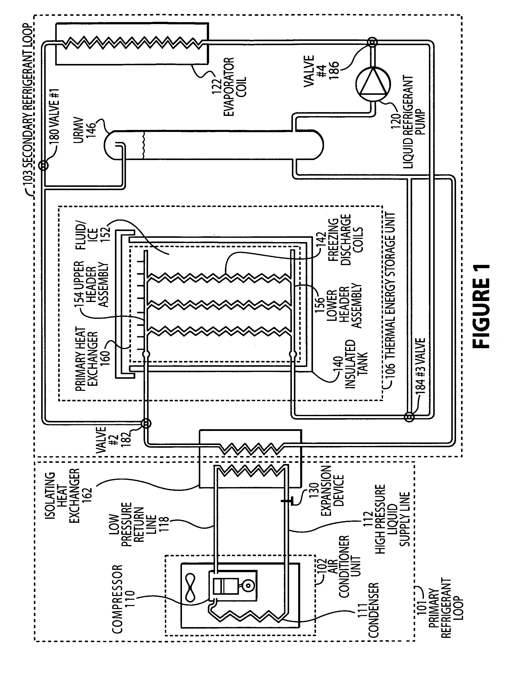
[0021]The disclosed embodiments overcome the disadvantages and limitations of the prior art by providing a refrigerant-based thermal storage system method and device wherein a condensing unit and an ice-tank heat exchanger can be isolated through a second heat exchanger. As illustrated in FIG. 1, an air conditioner unit 102 utilizing a compressor 110 to compress cold, low pressure refrigerant gas to hot, high-pressure gas. Next, a condenser 111 removes much of the heat in the gas and discharges the heat to the atmosphere. The refrigerant comes out of the condenser as a warm, high-pressure liquid refrigerant delivered t...


PUM


Abstract

Disclosed are a method and device for a refrigerant-based thermal storage system wherein a condensing unit and an ice-tank heat exchanger can be isolated through a second heat exchanger. The disclosed embodiments provide a refrigerant-based ice storage system with increased reliability, lower cost components, and reduced power consumption compared to a single phase system such as a glycol system.

Description

CROSS REFERENCE TO RELATED APPLICATIONS[0001]This application is a continuation-in-part of U.S. patent application Ser. No. 11 / 208,074 entitled “Thermal Energy Storage and Cooling System with Secondary Refrigerant Isolation” by Ramachandran Narayanamurthy, filed Aug. 18, 2005, which claims the benefit of and priority to U.S. Provisional Patent Application Ser. No. 60 / 602,774, entitled “Refrigerant-Based Energy Storage and Cooling System with Secondary Refrigerant Isolation”, filed Aug. 18, 2004. The entire contents of the above listed applications are hereby specifically incorporated herein by reference for all they disclose and teach.BACKGROUND OF THE INVENTION[0002]a. Field of the Invention[0003]The present invention relates generally to cooling systems, and more specifically to thermal energy storage air conditioning systems.[0004]b. Description of the Background[0005]With the increasing demands on peak demand power consumption, ice storage has been utilized to shift air conditio...

Claims


Application Information

Patent Timeline
Patent Type & Authority Patents(United States)
IPC IPC(8): F25D3/00
CPCF24F5/0017F25D16/00F25D17/02F24F2005/0067F25B25/005Y02E60/147F25B2400/24Y02E60/14
Inventor NARAYANAMURTHY, RAMACHANDRANWILLIS, JR., ROBERT R.
Owner ACP THULE INVESTMENTS LLC
Why Eureka
Try Eureka