
Internal pressure simulator for pressure sensors

a pressure sensor and simulator technology, applied in the field of pressure sensors, can solve the problems of inability to meet the requirements of the system, and inability to meet the requirements of the system, and achieve the effect of simple and cost-effective production and implementation

Inactive Publication Date: 2008-09-09
BROSH AMNON
View PDF6 Cites 9 Cited by
  • Summary
  • Abstract
  • Description
  • Claims
  • Application Information

AI Technical Summary

Benefits of technology

[0007]The present invention relates generally to pressure sensors, preferably oil-filled pressure sensors, having a pressure generating means for facilitating performance testing and self-calibration. The pressure sensor of the present invention is designed to allow testing and self-calibration of the pressure sensor without taking it off-line or disrupting service. The pressure generating means of the present invention is constructed to fit inside reasonably sized pressure sensors, and is simple and cost effective to make and implement.

Problems solved by technology

Unless the pressure sensors are removed and tested ex-situ, performance deterioration can result from long-term drifts, internal leaks, aging effects, standard wear and tear, and the like.
Such deterioration can jeopardize overall system performance.
This creates an unacceptable risk especially for critical applications in the areas of aviation, naval, automotive, medical, and the like.
This form of maintenance involves disruption in service and requires costly manual labor.

Method used


Image

  • Internal pressure simulator for pressure sensors
  • Internal pressure simulator for pressure sensors
  • Internal pressure simulator for pressure sensors

Examples


Embodiment Construction

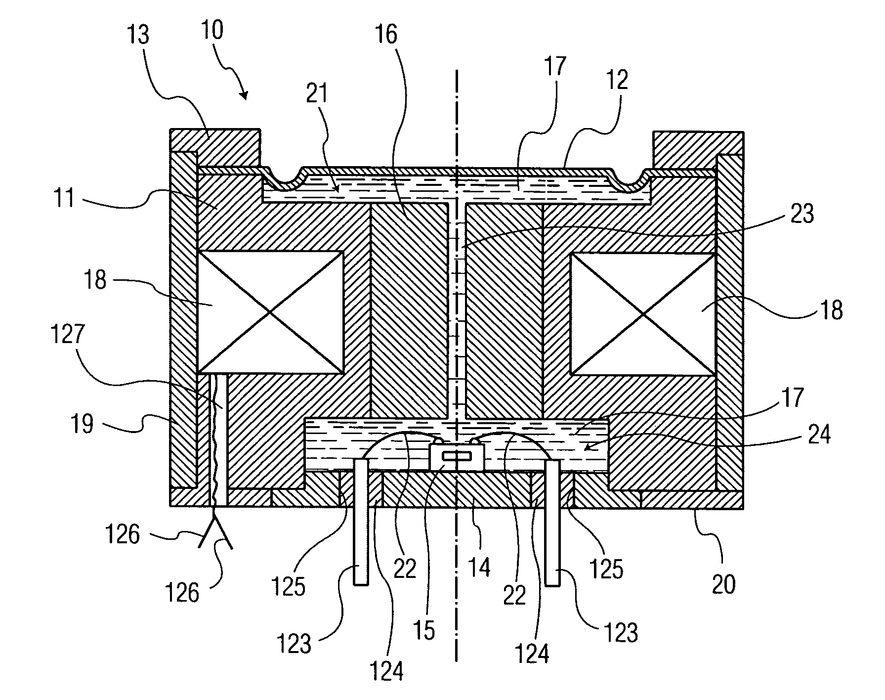
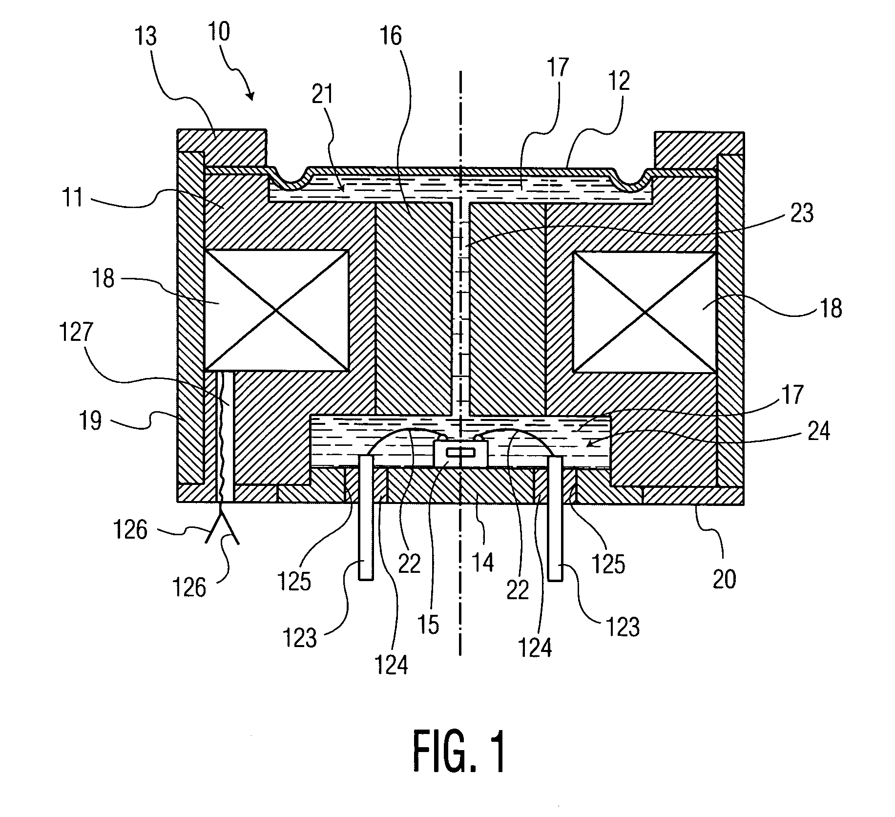
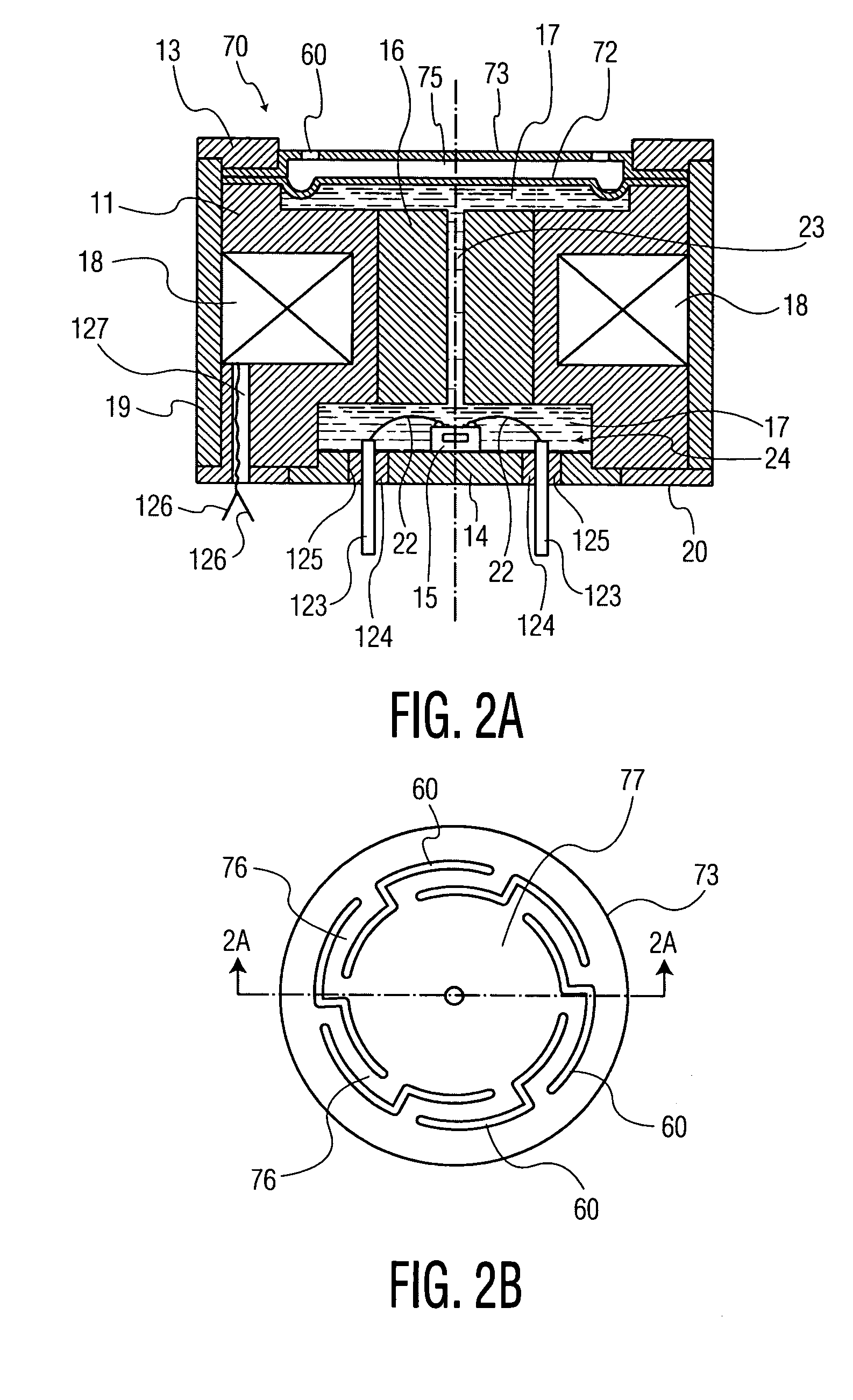
[0028]The present invention relates generally to pressure sensors, preferably oil-filled pressure sensors, having a pressure generating means for facilitating performance testing and self-calibration. The pressure sensor of the present invention is designed to allow testing and self-calibration of the pressure sensor without taking it off-line or disrupting service. The pressure generating means of the present invention is constructed to fit inside reasonably sized pressure sensors, and is simple and cost effective to make and implement. Typically, such sensors have cylindrical housings, but can also be square or rectangular.

[0029]The pressure sensor of the present invention is preferably an oil-filled pressure sensor. The oil-filled pressure sensor comprises a pressure sensing capsule, preferably in the form of a microelectromechanical system (MEMS) piezoresistive die or a capacitive sensor, enclosed in an oil-filled housing, a compliant isolation diaphragm operatively coupled to t...


PUM

PropertyMeasurementUnit
pressureaaaaaaaaaa
temperatureaaaaaaaaaa
temperaturesaaaaaaaaaa

Abstract

In oil-filled pressure sensors, the measured pressure is applied to a compliant isolation diaphragm, which causes the pressure of the internal oil to increase until it equals the external pressure. The pressure is sensed by a pressure sensing capsule, such as a MEMS piezoresistive pressure sensor. The invention incorporates an electromagnetic force generator, such as a coil and a magnetic core, within the pressure sensor in order to generate simulated pressure. When the coil is energized, the electromagnetic field creates a uniform distributed force, which moves the isolation diaphragm directly, or via an external flexure, in a manner to cause the pressure of the internal oil to increase, which is sensed by the pressure sensing capsule, which responds by producing an output signal proportional to the electromagnetic force. The simulated pressure is employed in order to perform sensor operation monitoring and self-calibration via measurement of the output signal.

Description

RELATED APPLICATION[0001]The present invention is related to and takes priority from co-pending Provisional Application No. 60 / 730,343, filed on Oct. 27, 2005, the teachings of which are incorporated herein to the extent they do not conflict herewith.FIELD OF THE INVENTION[0002]The present invention relates to devices useful for sensing pressure, and more particularly to a pressure sensor having a simulated pressure generator to facilitate performance testing and self-calibration.BACKGROUND OF THE INVENTION[0003]Pressure sensors measure pressure, typically of gases or fluids, at a point in the fluid network. Pressure sensors are used in a range of applications including, for example, medical devices and avionics. Such pressure sensors, including oil-filled pressure sensors, are manufactured and tested in the factory to ensure that they meet the mandatory specifications. The performance and / or calibration of pressure sensors must be periodically checked or tested. Unless the pressure...

Claims


Application Information

Patent Timeline
Patent Type & Authority Patents(United States)
IPC IPC(8): G01L9/10
CPCG01L9/0085G01L27/005G01L19/0645G01L9/06
Inventor BROSH, AMNON
Owner BROSH AMNON
Learn More