
Printing paper winding device

a winding device and printing paper technology, applied in printing presses, thin material processing, printing, etc., can solve the problems of limiting the base material of printing paper, printing paper may rupture, bending stress or bending pressure accompanies the winding operation, etc., and achieves the effect of low resistance to bending stress

Active Publication Date: 2008-09-09
SATO CO LTD
View PDF4 Cites 9 Cited by
  • Summary
  • Abstract
  • Description
  • Claims
  • Application Information

AI Technical Summary

Benefits of technology

"The present invention provides a printing paper winding device that can wind up any printing paper, including paper with low resistance to bending stresses. The device can wind up printing paper that carries labels with RFID tags or labels that have IC chips. It can also wind up printing paper that has poor resistance to bending stresses. The device can be independently controlled and can appropriately wind up printing paper on which printing has been performed and which has been discharged from any printer. The invention also includes a winding apparatus that can wind up a continuous web with bending angles that minimize bending stresses. The device can detect and control the position of the tension roller, which can apply tension to the printing paper by moving through a prescribed tension region during the winding process. The device can also include a sensor plate that can detect the bending angle of the winding path of the printing paper. The invention provides a solution for reducing bending stresses on the web and expanding the range of base material types of printing paper that can be wound up."

Problems solved by technology

The resulting problem is that bending stresses or bending pressure accompanies the winding operation.
This may limit the base material of the printing paper to one that can withstand the winding tension caused by a large bending stress applied in the zone of the reciprocation path where the winding path of the paper bends at an acute angle.
This has caused problems in that the printing paper may rupture or the labels attached to the base paper may prematurely peel off, instead of the printing paper with the intact labels thereon being wound onto the winding spindle.
Furthermore, when the printing paper support labels (RFID labels) that have IC chips placed thereon in which data can be read and written remotely, if the winding path of the printing paper is bent at a very acute angle, disconnection of the RFID label from the continuous paper or fracture of the IC chip can occur, when the tension roller is shifted along a movement or reciprocation range.
Such a RFID tag or label has a disadvantage in that the antenna may be bent or its junction connecting the IC chip to the antenna part may be broken in the bending of the web or of the paper web at a sharp or acute angle.
Therefore, such a winding device does not function to appropriately wind up the printing paper printed by and discharged from any printer, and the device lacks versatility for forming combinations with printers.

Method used


Image

  • Printing paper winding device
  • Printing paper winding device
  • Printing paper winding device

Examples


Embodiment Construction

[0056]In accordance with the present invention, a drive unit is controlled so as to limit the position of a tension roller to a tension region in which winding of a printing paper web can be conducted in the direction such that the bending angle of the winding path that bends to the winding of the printing paper defines a more obtuse angle and thus the web bends at a less acute angle. This enables operation of a printing paper winding device that is suitable for winding even printing paper with a low resistance to bending stresses.

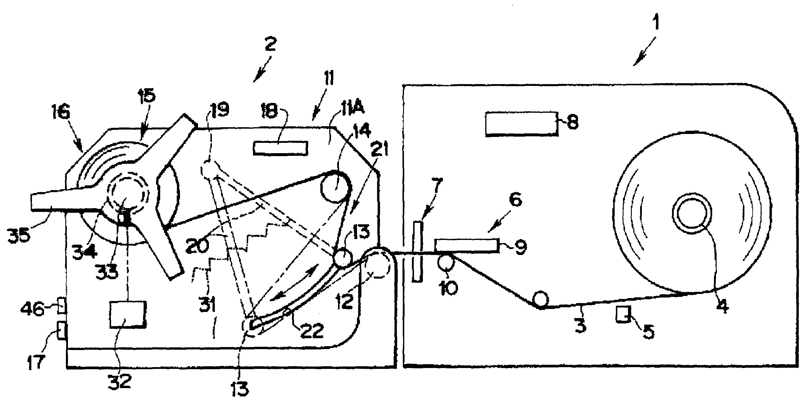
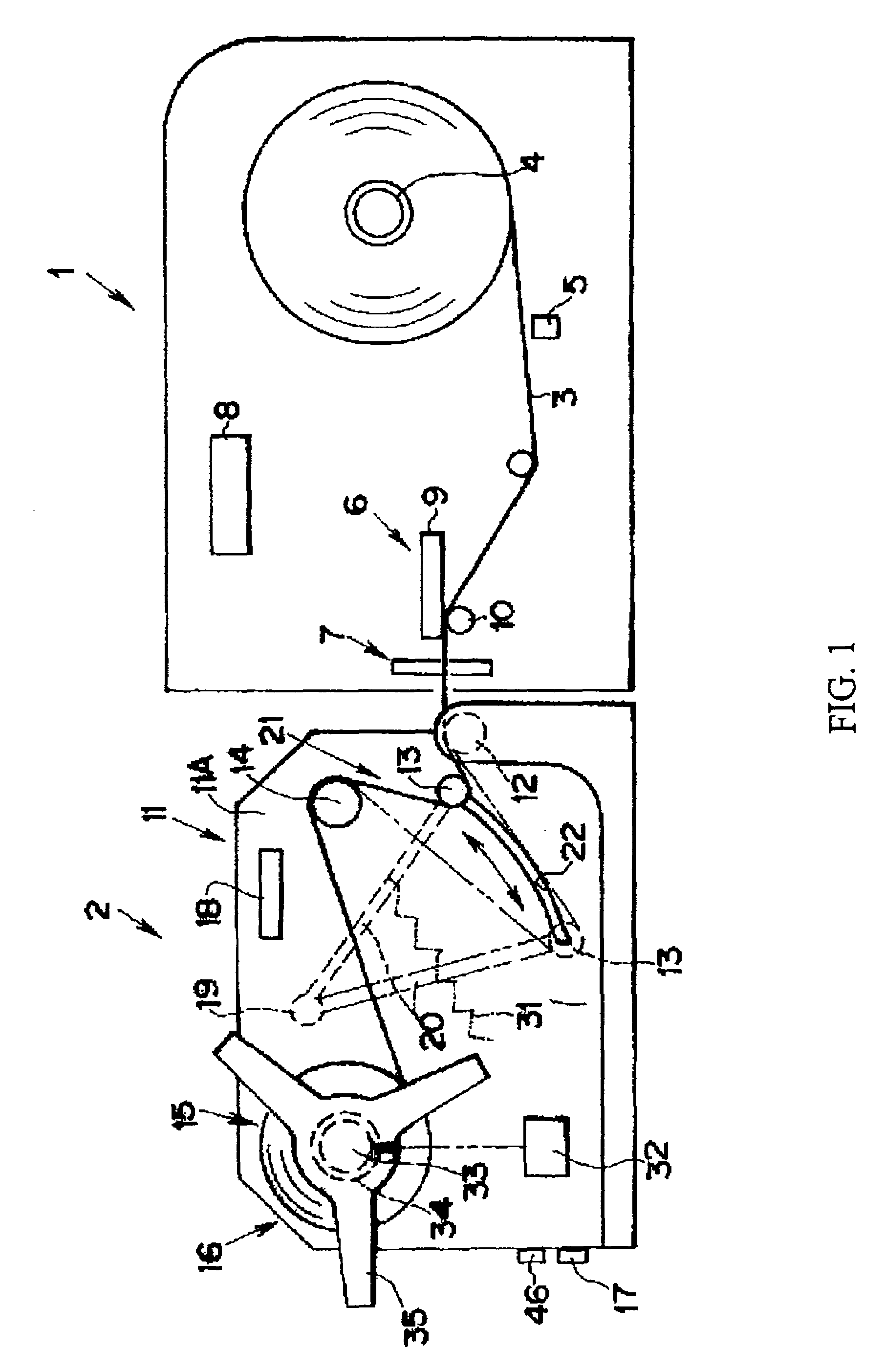
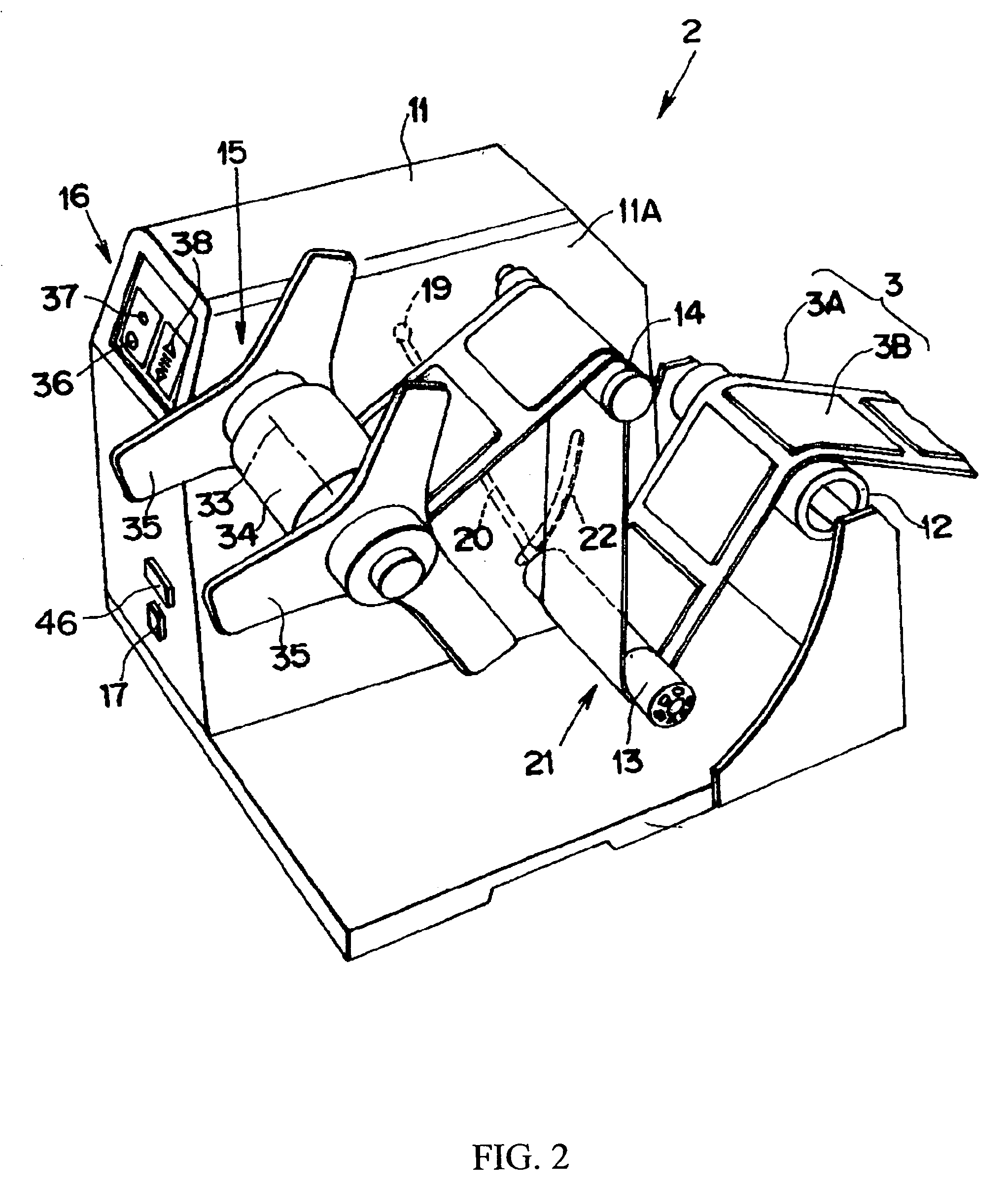
[0057]The printing paper winding device 2 of an embodiment of the present invention is explained below with reference to FIG. 1 to FIG. 8.

[0058]FIG. 1 is a schematic side view of a printer 1 and of a printing paper winding device 2 connected to the printer 1. The printer 1 has a supply unit 4 for printing paper 3. That paper is provided thereon, for example, with labels or tags. A detector 5 detects the position of the printing paper 3, and particularly th...


PUM


Abstract

A printing paper winding device for enabling winding of printing paper even paper with a base material having a low resistance to bending stresses or printing paper having RFID labels carrying IC chips. Bending stresses are reduced by dividing the movement region of the tension roller into four regions in order to enable the successive detection of the position or posture of the tension roller and by making the bending angle of the printing paper in the winding path close to a more obtuse angle. A winding control unit of the present invention determines whether the tension region where the tension roller is positioned is a first tension region, second tension region, third tension region, or fourth tension region, controls the drive unit to limit the tension roller to a tension region in which winding is possible in the direction such that the bending angle of the printing paper in the winding path, which follows the winding of the printing paper, is close to a more obtuse angle.

Description

CROSS REFERENCE TO RELATED APPLICATIONS[0001]The present invention is a continuation of International Application No. PCT / JP2005 / 021719, filed Nov. 25, 2005 and International Application No. PCT / JP2005 / 023784, filed Dec. 26, 2005, which claim priority to Japanese Patent Application No. 2004-347631, filed Nov. 30, 2004 and Japanese Patent Application No. 2004-377632, Dec. 27, 2004, respectively.BACKGROUND OF THE INVENTION[0002]1. Field of the Invention[0003]The present invention relates to a printing paper winding device, and more particularly to a printing paper winding device that is independent of a printer that prints on printing paper that is wound by the winding device. More particularly, the invention relates to apparatus for controlling tension on the web of paper being wound. The apparatus includes a tension roll that applies a controllable tension during winding of the continuous web.[0004]Further, the winding device is useful for continuously winding a continuous web of pa...

Claims


Application Information

Patent Timeline
Patent Type & Authority Patents(United States)
IPC IPC(8): B41J11/00B41F13/54B41J15/00
CPCB65H18/10B65H26/04B65H23/1955
Inventor KOEDA, AKIHIROKOJIMA, MASAHIROUCHIDATE, TADANOBUTAKEUCHI, SAKAETABATA, TSUTOMUSUZUKI, KAZUYA
Owner SATO CO LTD
Learn More