Medical/dental suction nozzle holster

a technology for medical/dental suction holsters and nozzles, which is applied in the direction of candle holders, saliva removers, lighting support devices, etc., can solve the problems of not being able to rotate the sleeves with respect, and the construction does not permit vertical rotation of the sleeves, so as to facilitate human thumb/finger gripping and prevent thumb/finger slippage

Active Publication Date: 2008-09-09
PATIENT SHIELD CONCEPTS LLC
View PDF33 Cites 10 Cited by
  • Summary
  • Abstract
  • Description
  • Claims
  • Application Information

AI Technical Summary

Benefits of technology

[0013]The medical / dental suction nozzle holster device of this patent disclosure is particularly characterized by the fact that it has three separate and distinct operating positions. Each of these operating positions places the holster device—and hence, the medical / dental suction nozzle that the device holds—in an operating position that a medical / dental practitioner finds most convenient and / or practical. For example, it can be readily adapted for use by left-handed as well as right-handed practitioners. Moreover, the holster device can be readily changed back and forth between its three possible operating positions without the use of hand tools or hand tightening knobs that operate bolts and the like—that sometimes unexpectedly loosen during use in medical / dental operations.
[0014]These advantages are achieved through selective use of the two main components of applicants' invention. The first main component is a holster component having a holster mounting mechanism that further comprises a rear plate having a keyway slot / nub receiver opening system. The second main component is a mounting channel component. The mounting channel component provides the means by which the operating position of the holster component can be initially selected and / or changed. To these ends, the face side of a front vertical plate of the mounting channel is provided with three separate and distinct key plate / key nub systems. Each of these key plate / key nub system may be readily inserted into (or removed from) the keyway slot / nub receiver opening system located in the rear plate of the holster mounting mechanism.
[0017]Next, it should be noted that an upper part of the rear vertical plate projects above the intersection of the horizontal ledge with the rear vertical plate while a lower part of the rear vertical plate projects below the horizontal ledge / rear vertical plate intersection. In effect, the inside surface of the upper part of the rear vertical wall serves as the front side of the rear vertical plate that forms the other side wall of the bottom mounting channel region. As will be better seen in FIG. 9, the lower part of the rear vertical plate serves as a lever arm used to lower the upper part of the rear vertical plate. To this end, the outside surface of the lower part of the rear vertical plate can be further provided with a surface suitable for human thumb / finger contact. For example this surface can be given a roughened surface to prevent thumb / finger slippage from this outside surface of the lower part of the rear vertical plate. The lower end of the rear vertical plate also can be provided with a projecting ledge or extended nub to facilitate human thumb / finger gripping of the lower part of the rear vertical plate. These thumb / finger contact enhancing features are not essential to the use of this medical / dental suction nozzle holster device, but they are very practical optional features. This follows from the fact that the holster device is often mounted to a side rail (and dismounted from such a rail) by hands residing in wet surgical gloves.

Problems solved by technology

Such an arrangement does not permit rotation of the sleeve with respect to the dovetail track's channel portion.
This construction does not permit vertical rotation of the sleeve to any alternative position or orientation.
It might again be noted that none of these devices for attaching medical / dental holsters to a mounting surface (e.g., an operating room table or wall) allow for variation in the vertical orientation of the handle of the suction nozzles held in such holsters.

Method used


Image

  • Medical/dental suction nozzle holster
  • Medical/dental suction nozzle holster
  • Medical/dental suction nozzle holster

Examples


Embodiment Construction

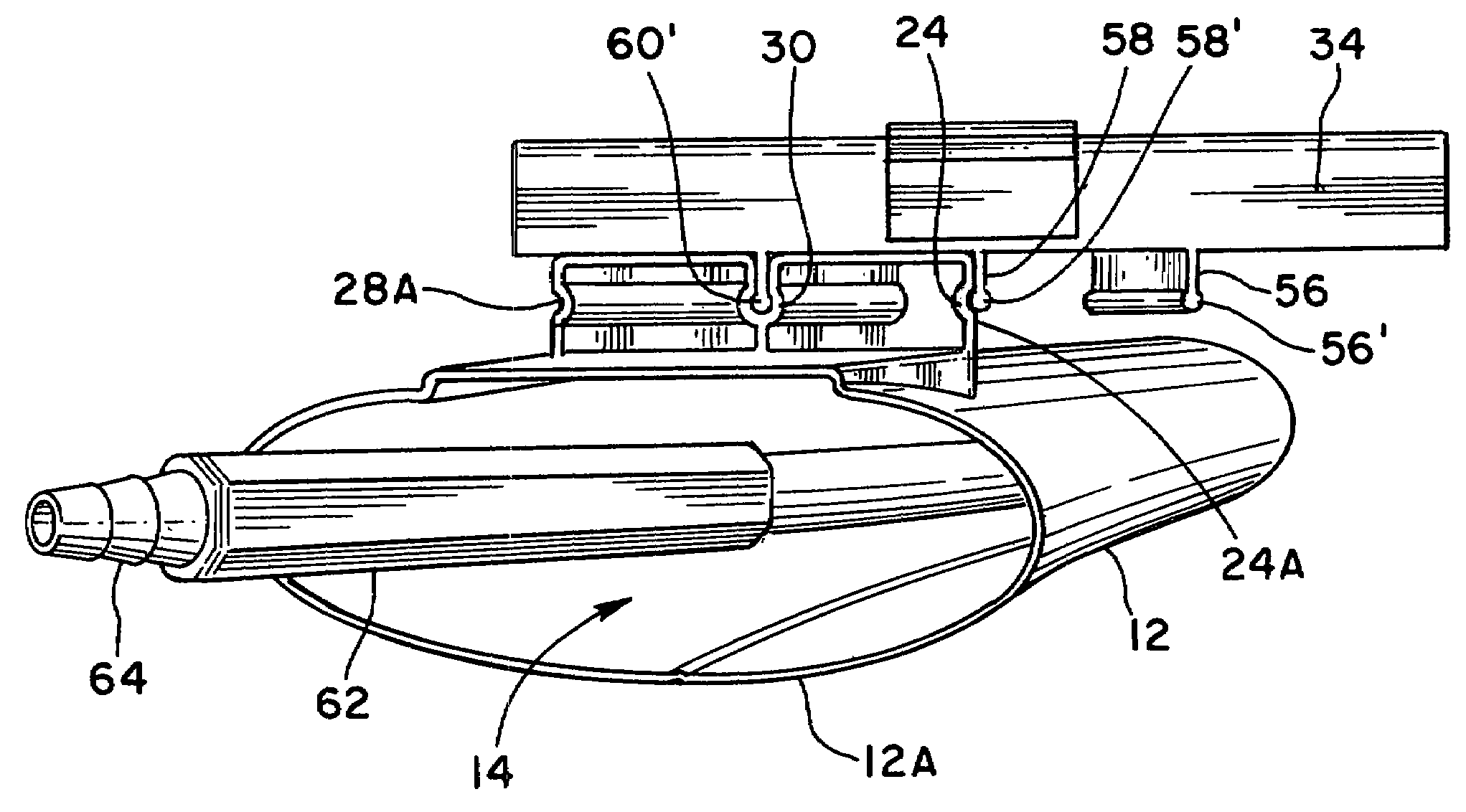
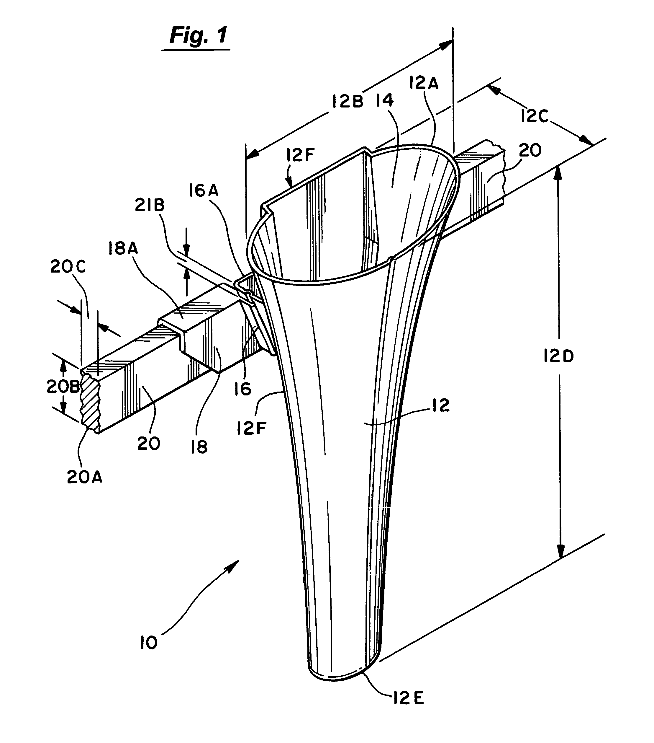
[0027]FIG. 1 depicts a medical / dental suction nozzle holster device 10 made and assembled according to certain teachings of this patent disclosure. This holster device 10 has a holster component 12 that generally defines an inwardly and downwardly constricted holster cavity 14 for receiving a front end of a suction nozzle e.g., a medical suction nozzle of the Yankauer type (not shown). The top lip 12A of the holster component 12 is shown in FIG. 1 as having a generally elliptical configuration. The long diameter 12B of such an elliptical configuration will preferably be from about 3 to about 6 inches (and more preferably from about 4-5 inches). The short diameter 12C of the elliptical configuration will preferably be from about 1.5 to about 3 inches (and more preferably from about 1.5 to about 2.0 inches). The holster component 12 will have a depth 12D that will preferably range from about 5.0 to about 13 inches (and more preferably from about 9.0 to about 11.0 inches). The body of ...


PUM


Abstract

A suction nozzle holster device is provided with three possible operating positions through the use of a mounting channel component having a left, a center and a right key plate / key nub system that can each be respectively inserted into a cooperating keyway slot / nub receiver opening system mounted on a rear portion of a holster mounting component of the device. This arrangement gives the holster device three distinct operating positions.

Description

BACKGROUND OF THE INVENTION[0001]1. Field of the Invention[0002]This invention is generally concerned with holsters for the nozzle components of medical / dental suction devices. It is particularly concerned with maintaining aseptic conditions and convenient human hand access to such devices during medical / dental procedures.[0003]2. Discussion of the Background[0004]A wide variety of prior art medical suction nozzle holsters are disclosed in the patent literature. Such holders have many different features that perform various distinct technical functions as well as various convenience-in-use functions. These convenience-is-use functions often involve the methods and mechanical devices used to temporarily attach such nozzle holsters to a bedrail or operating table rail for ease and / or convenience of use during medical / dental procedures wherein the medical / dental practitioner's attention is often urgently directed away from such holsters.[0005]For example, U.S. Pat. No. 6,367,110 B1 (“t...

Claims


Application Information

Patent Timeline
Patent Type & Authority Patents(United States)
IPC IPC(8): A61C13/38A41F5/00
CPCA61C19/00A61B19/0256A61C17/043A61B50/20A61C17/08
Inventor WHITE, LYNN R.SAMSON, JEFFREY T.OSBURN, JAMES V.
Owner PATIENT SHIELD CONCEPTS LLC
Why Eureka
Try Eureka