Electric connection box

a technology of connection box and wire harness, which is applied in the direction of coupling device connection, coupling device details, printed circuits, etc., can solve the problems of low inability to carry out easily, waste of resources, etc., and achieves marked enhancement of efficiency of assembling operation, the effect of enhancing the efficiency of the operation of fixing the wire harness to the holding portion of the harness by the fixing member

Inactive Publication Date: 2008-09-09
YAZAKI CORP
View PDF6 Cites 25 Cited by
  • Summary
  • Abstract
  • Description
  • Claims
  • Application Information

AI Technical Summary

Benefits of technology

[0010]This invention has been made in view of the above circumstances, and an object of the invention is to provide an electric connection box in which the efficiency of an assembling operation, in which a wire harness extending from a lower surface of a connection box body is bent so as to be led downwardly out of the lower cover, with the lower cover attached to a lower portion of the connection box body, is enhanced, and also a surplus portion of the wire harness which has been required for attaching a side cover to the lower cover can be completely eliminated.
[0023]The electric connection box of the construction of the above Paragraph (1) includes the harness holding portion formed on the lower wall and extending downwardly from the lower cover, and the fixing member fixing the wire harness, led out through the harness lead-out through hole, to the harness holding portion. Therefore, even if the wire harness is thick, and can not easily be bent, it is only necessary to fix the wire harness to the harness holding portion of the lower cover by the fixing member and then to attach the side cover to the lower cover. And besides, the wire harness will not be unduly twisted, and therefore the efficiency of the assembling operation is good. Furthermore, in the electric connection box of the construction of the above Paragraph (1), a surplus portion of the wire harness which has heretofore been required for attaching the side cover to the lower cover can be completely eliminated, and this can save resources.
[0025]In the electric connection box of the construction of the above Paragraph (3), the harness holding portion extends from the portion of the lower wall defining the opening of the harness lead-out through hole, and therefore the radius of curvature of the bent portion of the wire harness can be easily made small. Therefore, the bulging of the bent portion of the wire harness toward the side cover can be suppressed, and therefore the wire harness will not prevent the mounting of the side cover on the lower cover.
[0026]In the electric connection box of the construction of the above Paragraph (4), the upper surface of the lower wall of the lower cover is the slanting surface slanting downwardly toward the opening of the harness lead-out through hole formed in the lower wall, and therefore the bending of the wire harness required for the leading of the wire harness downwardly out of the lower cover can be made gentle. Therefore, the efficiency of the operation for fixing the wire harness to the harness holding portion by the fixing member is markedly enhanced.
[0027]In the present invention, the efficiency of the assembling operation, in which the wire harness extending from the lower surface of the connection box body is bent so as to be led downwardly out of the lower cover, with the lower cover attached to the lower portion of the connection box body, is enhanced, and also a surplus portion of the wire harness which has been required for attaching the side cover to the lower cover can be completely eliminated.

Problems solved by technology

In such an electric connection box, particularly when the wire harness is so thick as not to be easily bent, the worker must engage the engagement portions of the lower cover with the respective retaining portions of the connection box body with a larger force against the spring back of the wire harness (that is, an elastic restoring force of the wire harness), that is, in a manner to forcibly press the side cover, and this engaging operation can not be carried out easily, and therefore the efficiency of the assembling operation is low.
Furthermore, the wire harness need to have a surplus portion for bringing the engagement portions of the side cover into engagement with the respective retaining portions of the lower cover, and this is a waste of resources.

Method used


Image

  • Electric connection box
  • Electric connection box
  • Electric connection box

Examples


Embodiment Construction

” with reference to the accompanying drawings.

BRIEF DESCRIPTION OF THE DRAWINGS

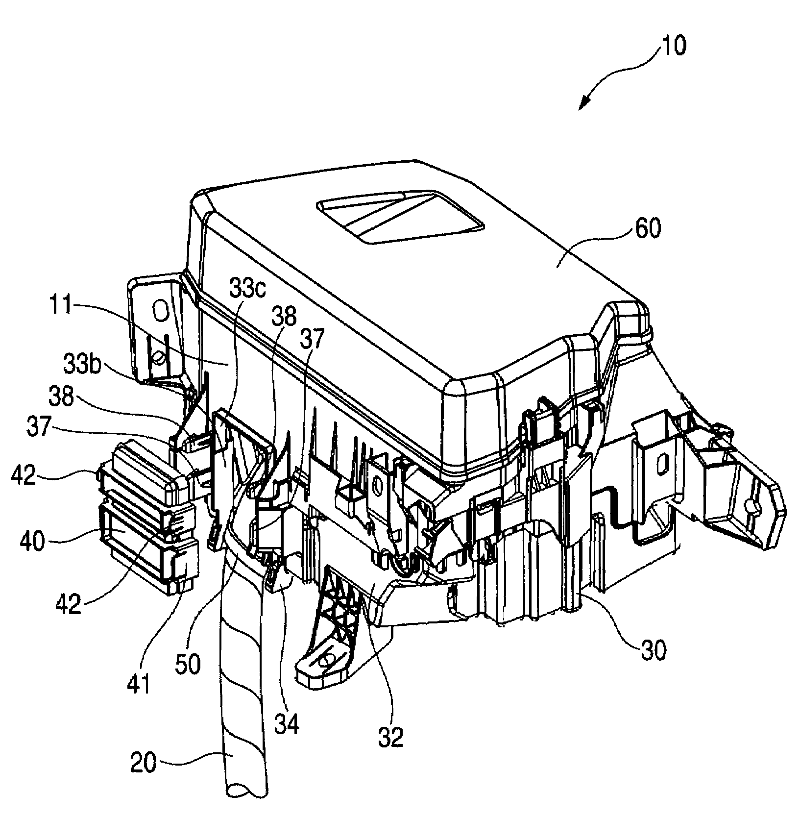
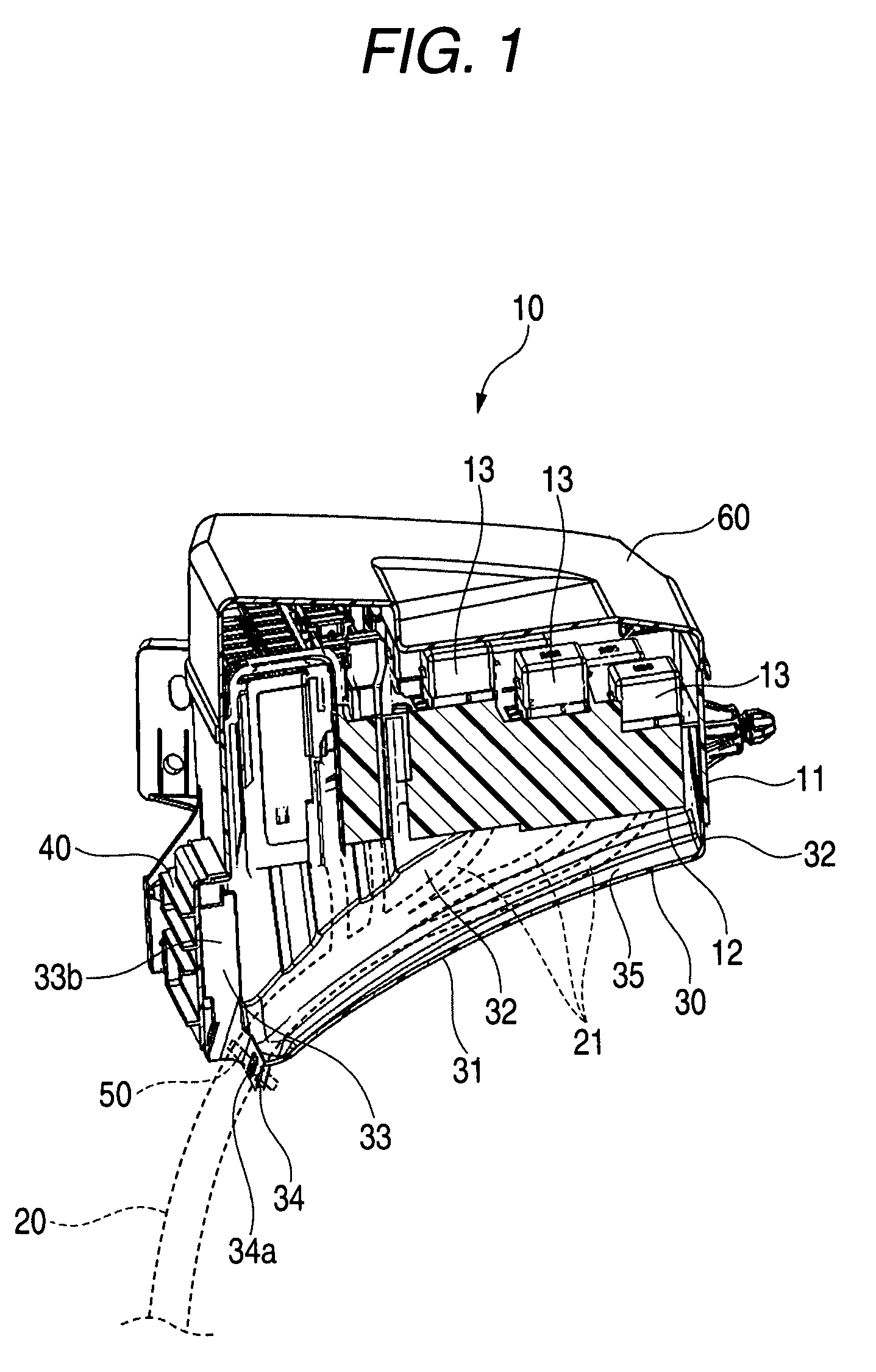
[0029]FIG. 1 is a vertical cross-sectional view of one preferred embodiment of an electric connection box of the present invention.

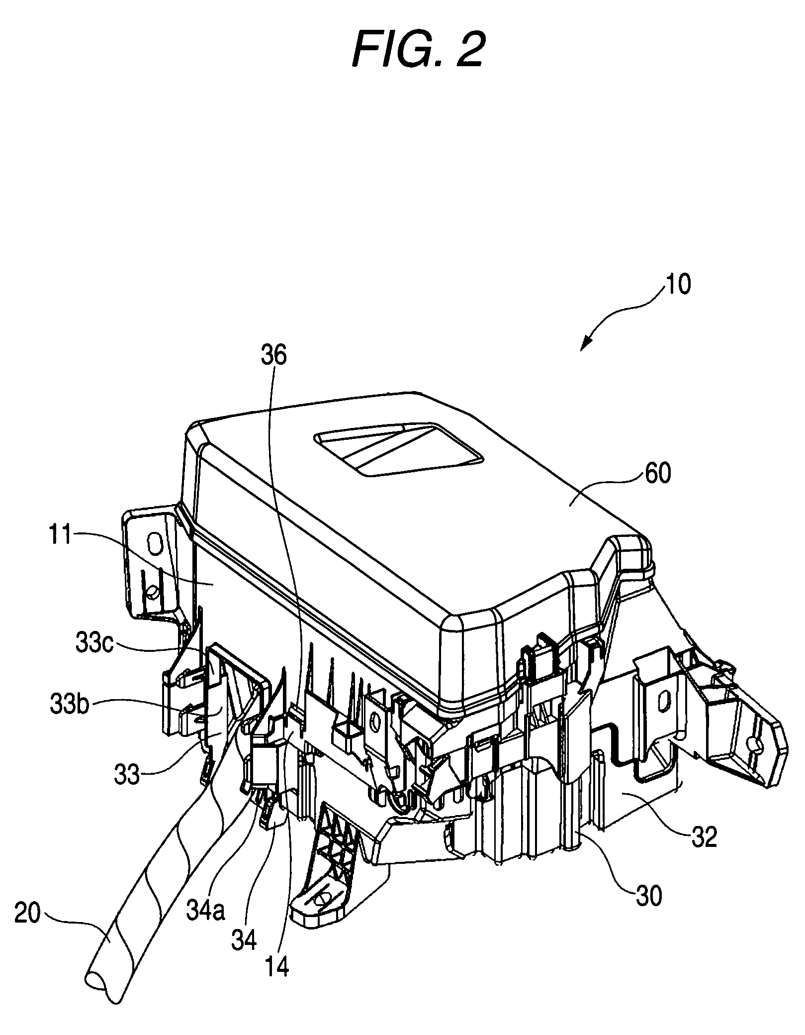
[0030]FIG. 2 is a perspective view of the electric connection box explanatory of an operation for the leading-out of a wire harness in an operation for assembling the electric connection box of FIG. 1, showing a condition in which a lower cover is attached to a lower portion of a connection box body, with the wire harness led to the exterior through a harness lead-out through hole.

[0031]FIG. 3 is a perspective view of the electric connection box explanatory of a step next to the wire harness leading-out operation of FIG. 2, showing a condition in which the wire harness led out through the harness lead-out through hole is bent, and is fixed to a harness holding portion of the lower cover by a fixing member.

[0032]FIG. 4 is a perspective view of the electric connection box explan...


PUM


Abstract

An electric connection box includes a harness holding portion formed on a lower wall of a lower cover and extending downwardly from the lower cover, and a fixing member which fixes a wire harness, led out through a harness lead-out through hole, to the harness holding portion.

Description

BACKGROUND OF THE INVENTION[0001]1. Field of the Invention[0002]This invention relates to an electric connection box (i.e., an electric junction box) such for example as a relay box, a fuse box and an electronic control unit box) used in a vehicle such as an automobile, and more particularly to an electric connection box in which a wire harness electrically connected to electrical parts (such as relays, fuses and, electronic control units) is bent in such a manner that a direction of leading of the wire harness out of the electric connection box is regulated to a predetermined direction.[0003]2. Related Art[0004]Electric connection boxes for automobiles are broadly classified into two kinds, that is, the type to be mounted within a passenger compartment and the type to be suitably mounted within an engine room. The electric connection box mounted within the passenger compartment will not basically be exposed to rain and others, and therefore it is not necessary to give much consider...

Claims


Application Information

Patent Timeline
Patent Type & Authority Patents(United States)
IPC IPC(8): H01R12/00
CPCH05K7/026H01R13/5833H01R2201/26H01R13/5841
Inventor KANEKO, NOBUTAKAMAEBASHI, AKEMI
Owner YAZAKI CORP
Why Eureka
Try Eureka