Gas system for wire feeding devices

a gas system and wire feeding technology, applied in the field of gas systems, can solve the problems of large size and weight of gas cylinders, affecting the portability of welders, and affecting the service life of gas cylinders, and achieve the effect of high portability

Active Publication Date: 2008-09-09
ILLINOIS TOOL WORKS INC
View PDF28 Cites 19 Cited by
  • Summary
  • Abstract
  • Description
  • Claims
  • Application Information

AI Technical Summary

Benefits of technology

[0011]The present invention is directed to a wire feeder having a shielding gas system that solves the aforementioned drawbacks. The wire feeder is constructed to provide a portable source of shielding gas to a weld. A pressure vessel is removeably supported by the wire feeder such that the wire feeder is efficiently and conveniently transportable by a single person and has a source of shielding gas securely supported thereby.
[0015]Therefore, the present invention provides a highly portable and versatile welding-type system having a shielding gas system that is lightweight and easily transportable. Various other features, objects and advantages of the present invention will be made apparent from the following detailed description and the drawings.

Problems solved by technology

The size and weight of the gas cylinders significantly detracts from the portability of the welder.
Additionally, attempts to move the welder and gas cylinder together presents an opportunity for inadvertent damage to the gas cylinder or to the regulator attached thereto unless a cart is provided.
Such carts however are large and typically constructed to accommodate bulky gas cylinders.
As such, the portability of the welding apparatus is limited by the portability of the shielding gas cylinder.
Though the components of the wire feeder are remotely positionable relative to the power source configured to generate the power signal suitable for welding-type applications, the portability of the wire feeder is limited by the connectivity of the wire feeder to a shielding gas source.
Either configuration limits the range of portability of the wire feeder by the length of gas hose extending between the gas source and the wire feeder.
As such, movement of the gas cylinder is often limited by an operator's physical ability of move the cylinder or the surrounding environment where the gas cylinder is to be moved.
That is, in certain work environments it may be impractical or impossible to maneuver the equipment necessary to move the gas cylinder to a desired location remote from the welding-device power source.

Method used


Image

  • Gas system for wire feeding devices
  • Gas system for wire feeding devices
  • Gas system for wire feeding devices

Examples


Embodiment Construction

[0029]As one skilled in the art will fully appreciate, the hereinafter description of welding devices not only includes welders but also includes any system that requires high power outputs that can benefit from the use of a compressed shielding gas. Such systems can include heating and cutting systems. Description of a welding-type apparatus or device illustrates just one embodiment in which the present invention may be implemented.

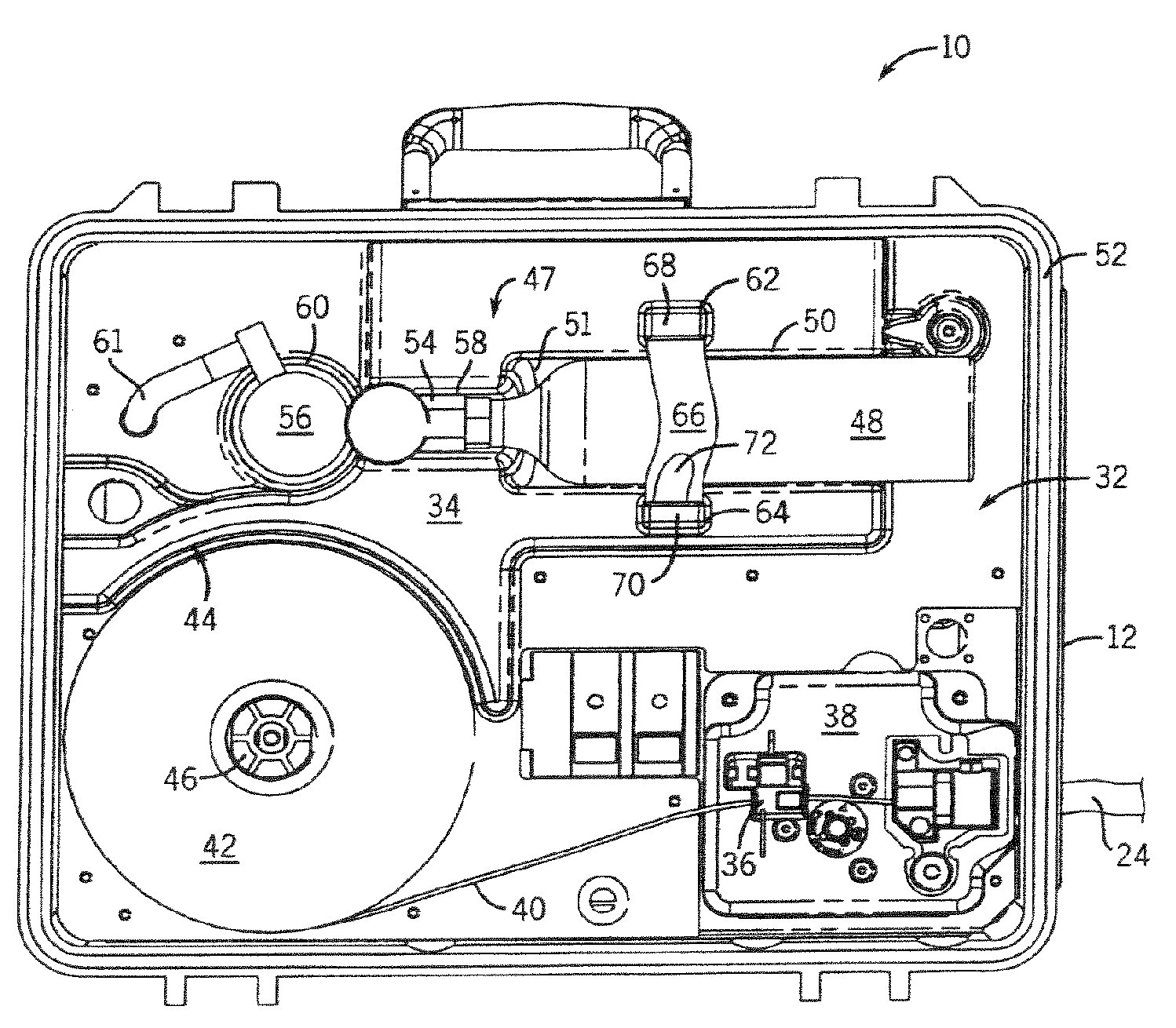
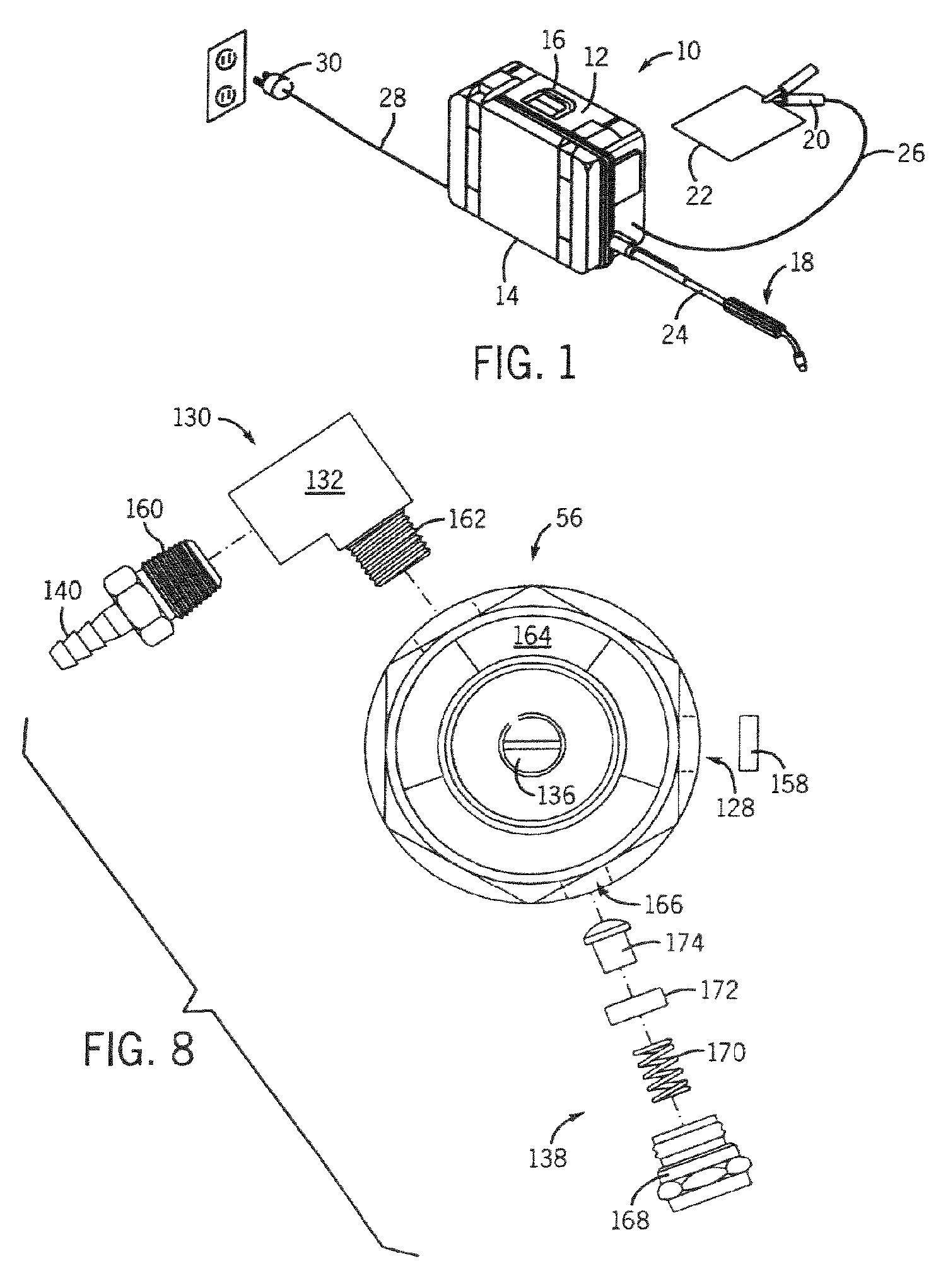
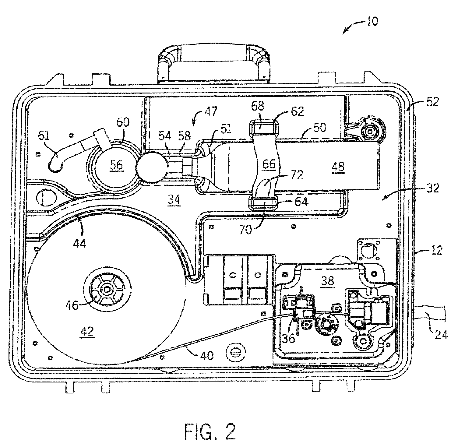
[0030]Referring to FIG. 1, a perspective view of a welding device incorporating the present invention is shown. Welding device 10 includes a housing 12 enclosing the internal components of the welding device under a cover 14. The welding device 10 includes a handle 16 for transporting the welding system from one location to another. Although shown as a “suitcase” welding device, capable of being easily transported by one person, the present invention is equally applicable to larger welding devices which may have more limited portability. To effectuate th...


PUM

PropertyMeasurementUnit
poweraaaaaaaaaa
pressureaaaaaaaaaa
welding poweraaaaaaaaaa

Abstract

A wire feeder and gas system for use therewith is shown. The gas system of the wire feeder includes a canister that is constructed to contain a shielding gas therein and is connectable to the wire feeder. The canister is supported by the wire feeder when it is connected thereto such that the wire feeder can be efficiently and conveniently transported from one location to another with the source of shielding gas securely connected thereto.

Description

CROSS-REFERENCE TO RELATED APPLICATIONS[0001]The present application is a Continuation in Part of U.S. patent application Ser. No. 10 / 709,540 filed on May 12, 2004.BACKGROUND OF THE INVENTION[0002]The present invention relates generally to welding systems and, more particularly, to a gas system for providing shielding gas to a weld.[0003]Welder power sources have become increasingly portable in recent years. This portability is largely the result of lighter unit weight and improved electrical components. One advancement in the area of electrical components has been the incorporation of inverter-type power sources. The application of an inverter power source has reduced the size and weight of welders and created usable space within the confines of the housing, while maintaining the ability to generate the outputs required for welding.[0004]Improvements in wire feeder technology have also improved the ease of use and portability of a welder. Wire welding is generally believed to be ea...

Claims


Application Information

Patent Timeline
Patent Type & Authority Patents(United States)
IPC IPC(8): B23K9/133B23K9/16B23K9/12B23K9/32
CPCB23K9/124B23K9/323B23K9/16B23K9/1333
Inventor STANZEL, KENNETH A.BREITBACH, JOHNWOODWARD, RONALD
Owner ILLINOIS TOOL WORKS INC
Why Eureka
Try Eureka