Particle accelerator and methods therefor

a technology of particle accelerator and accelerator, which is applied in the direction of accelerator, klystron, electric discharge tube, etc., can solve the problems of time-consuming and increase the manufacturing cost of linacs

Inactive Publication Date: 2008-09-09
HANNA SAMY M
View PDF8 Cites 11 Cited by
  • Summary
  • Abstract
  • Description
  • Claims
  • Application Information

AI Technical Summary

Problems solved by technology

This process is a time consuming and substantially increases the manufacturing cost of the linacs.

Method used


Image

  • Particle accelerator and methods therefor
  • Particle accelerator and methods therefor
  • Particle accelerator and methods therefor

Examples


Embodiment Construction

[0031]The present invention will now be described in detail with reference to a few preferred embodiments thereof as illustrated in the accompanying drawings. In the following description, numerous specific details are set forth in order to provide a thorough understanding of the present invention. It will be apparent, however, to one skilled in the art, that the present invention may be practiced without some or all of these specific details. In other instances, well known process steps and / or structures have not been described in detail in order to not unnecessarily obscure the present invention. The features and advantages of the present invention may be better understood with reference to the drawings and discussions that follow.

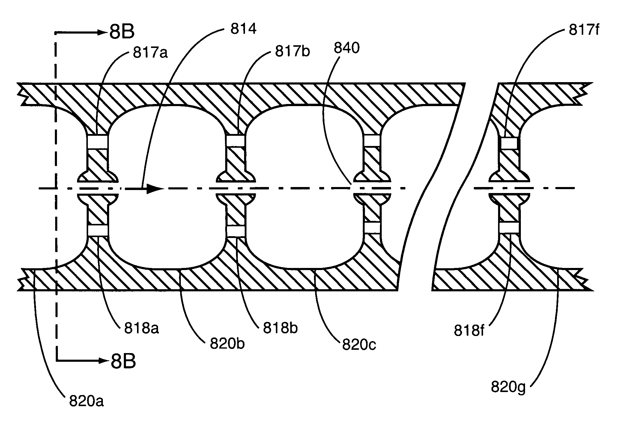
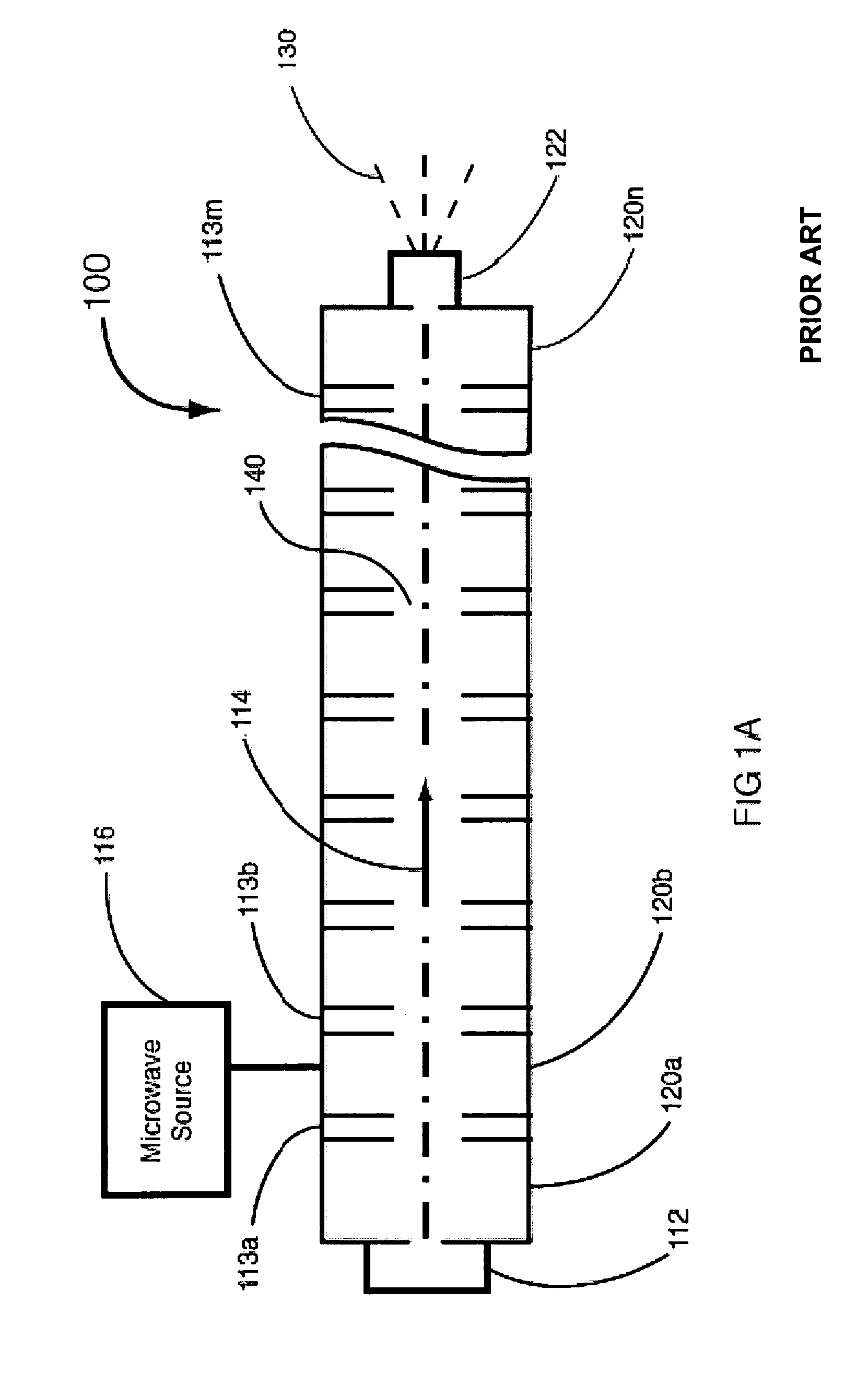
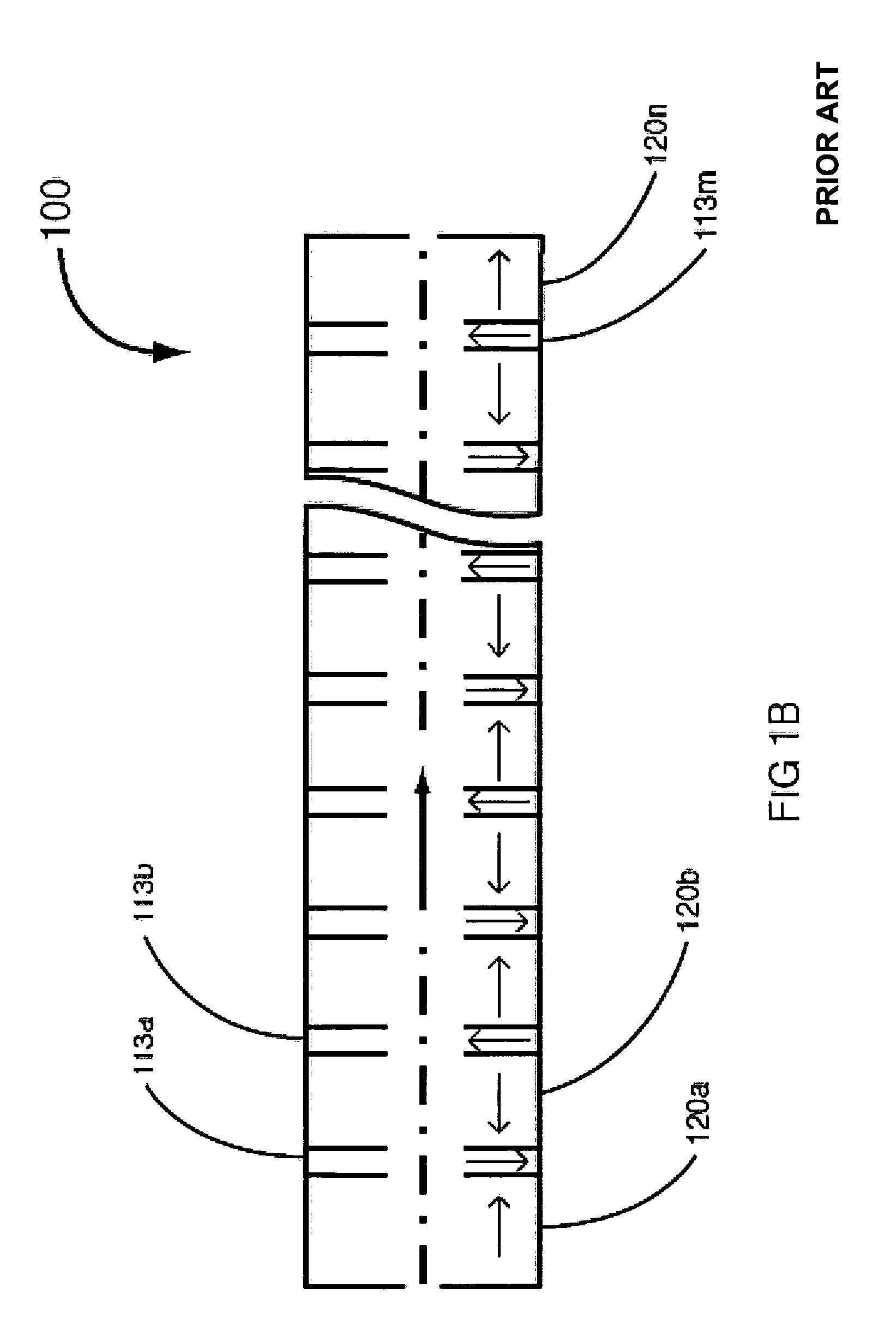
[0032]To facilitate discussion, FIGS. 5A, 5B, 6A-6C, 7A, 7B, 8A, 8B, and 9A-9E include block diagrams, graphs and sectional views which illustrate several embodiments of the linear accelerators of the present invention.

[0033]Historically, the prevailing ...


PUM


Abstract

Standing-wave linear accelerators (linac) having a plurality of accelerating cavities and which do not have any auxiliary cavities are provided. Such linacs are useful for industrial applications such as radiography, cargo inspection and food sterilization, and also medical applications such as radiation therapy and imaging. In one embodiment, the linac includes an electron gun for generating an electron beam, and a plurality of accelerating cavities which accelerates the electron beam by applying electromagnetic fields generated by a microwave source. At least two adjacent accelerating cavities of the plurality of accelerating cavities are coupled together by at least one resonant iris. The electromagnetic fields resonate through the plurality of accelerating cavities and the at least one resonant iris.

Description

BACKGROUND OF THE INVENTION[0001]The present invention relates to particle accelerators. More particularly, the present invention relates to cost effective particle accelerators for applications including industrial applications such as radiography, cargo inspection and food sterilization, and also medical applications such as radiation therapy and imaging.[0002]Particle accelerators operate by generating charged particles having a particular energy depending on the application. One exemplary particle accelerator is the standing-wave (SW) electron linear accelerator (linac) used in medical and industrial applications. FIG. 1A shows a simplified functional representation of a linac 100 which receives electrons from an electron gun 112. The electrons are accelerated to produce a high-energy electron beam 114 along an axial bore hole 140. Beam 114 is focused and accelerated in a series of accelerating cavities 120a, 120b . . . 120n by forces exerted on the electrons by microwave fields...

Claims


Application Information

Patent Timeline
Patent Type & Authority Patents(United States)
IPC IPC(8): H05H9/04
CPCH05H7/18H05H9/04H05H7/22
Inventor HANNA, SAMY M.
Owner HANNA SAMY M
Why Eureka
Try Eureka