Reader/writer

a technology of reader/writer and contactless tag, which is applied in the direction of burglar alarm mechanical actuation, burglar alarm by hand-portable article removal, instruments, etc., can solve the problem that the transmission power provided to the selected antenna coil in the reader/writer is not sufficiently transmitted to the antenna coil in the contactless tag, and cannot be efficiently communicated with the contactless tag located away from the reader/writer. the effect of efficient transmission of transmission power

Inactive Publication Date: 2008-09-09
138 EAST LCD ADVANCEMENTS LTD
View PDF5 Cites 19 Cited by
  • Summary
  • Abstract
  • Description
  • Claims
  • Application Information

AI Technical Summary

Benefits of technology

[0010]An advantage of the invention is to provide a reader / writer that can efficiently transmit the transmission power that is supplied to the selected antenna coil to the contactless tag in case where the single reader / writer uses the plurality of the antenna coils.
[0011]According to a first aspect of the invention, an reader / writer performing a two-way communication with a contactless tag through electromagnetic induction and supplying electric power to the contactless tag includes a plurality of antenna circuits, each of the plurality of antenna circuits having an antenna coil for electromagnetically coupling with an antenna coil in the contactless tag, a first amplifier circuit amplifying a signal which the antenna circuits transmits, a plurality of first switches, each of the plurality of first switches provided between the first amplifier circuit and each of the plurality of antenna circuits, a second amplifier circuit amplifying a signal which the plurality of antenna circuits received, a plurality of second switches provided between the second amplifier circuit and each of the plurality of antenna circuits, and a control circuit turning on a predetermined switch among the plurality of first switches and a predetermined switch among the plurality of second switches. The antenna coil has a loop shape and a plurality of the antenna coils are provided adjacently each other in the same plane, and the loop of the antenna coil has a shape such that an adjoining region of the antenna coils becomes as small as possible.
[0012]According to a second aspect of the invention, an reader / writer performing a two-way communication with a contactless tag through electromagnetic induction and supplying electric power to the contactless tag includes a plurality of antenna circuits, each of the plurality of antenna circuits having an antenna coil for electromagnetically coupling with an antenna coil in the contactless tag, a plurality of first amplifier circuits amplifying a signal which the antenna circuit transmits, a plurality of first switches, each of the plurality of first switches provided between each first amplifier circuit and each of the plurality of antenna circuits, a second amplifier circuit amplifying a signal which the antenna circuit received, a plurality of second switches, each of the plurality of second switches provided between the second amplifier circuit and each of the plurality of antenna circuits, and a control circuit turning on a predetermined switch among the plurality of first switches and a predetermined switch among the plurality of second switches. The antenna coil has a loop shape and the plurality of the antenna coils are provided adjacently each other in the same plane, and the loop of the antenna coil has a shape such that an adjoining region of the antenna coils becomes as small as possible.
[0013]In this case, it is preferable that the shape of the antenna coil included in the antenna circuit is a circular form.
[0014]It is also preferable that the first switch and the second switch are made of relay circuits with small parasitic impedance.
[0015]According to a third aspect of the invention, an reader / writer performing a two-way communication with a contactless tag through electromagnetic induction and supplying electric power to the contactless tag includes a plurality of antenna coils for electromagnetically coupling with an antenna coil in the contactless tag, a first amplifier circuit amplifying a signal which the plurality of antenna coils transmits, a plurality of matching circuits coordinating the plurality of antenna coils and the first amplifier circuit and made of an ungrounded circuit, a plurality of first switches, each of the plurality of first switches provided between each matching circuit and each of the plurality of antenna coils, a second amplifier circuit amplifying a signal which the plurality of antenna coils received and a plurality of second switches, each of the plurality of second switches provided between the second amplifier circuit and each of the plurality of antenna coils.

Problems solved by technology

However, it cannot efficiently communicate with the contactless tag located away from the reader / writer at the same time with the tag located near the reader / writer.
However, in this case, there could be a problem that the antenna coils interfere with each other.
Consequently, the transmission power provided to the selected antenna coil in the reader / writer is not sufficiently transmitted to the antenna coil in the contactless tag.

Method used


Image

  • Reader/writer
  • Reader/writer
  • Reader/writer

Examples


first embodiment

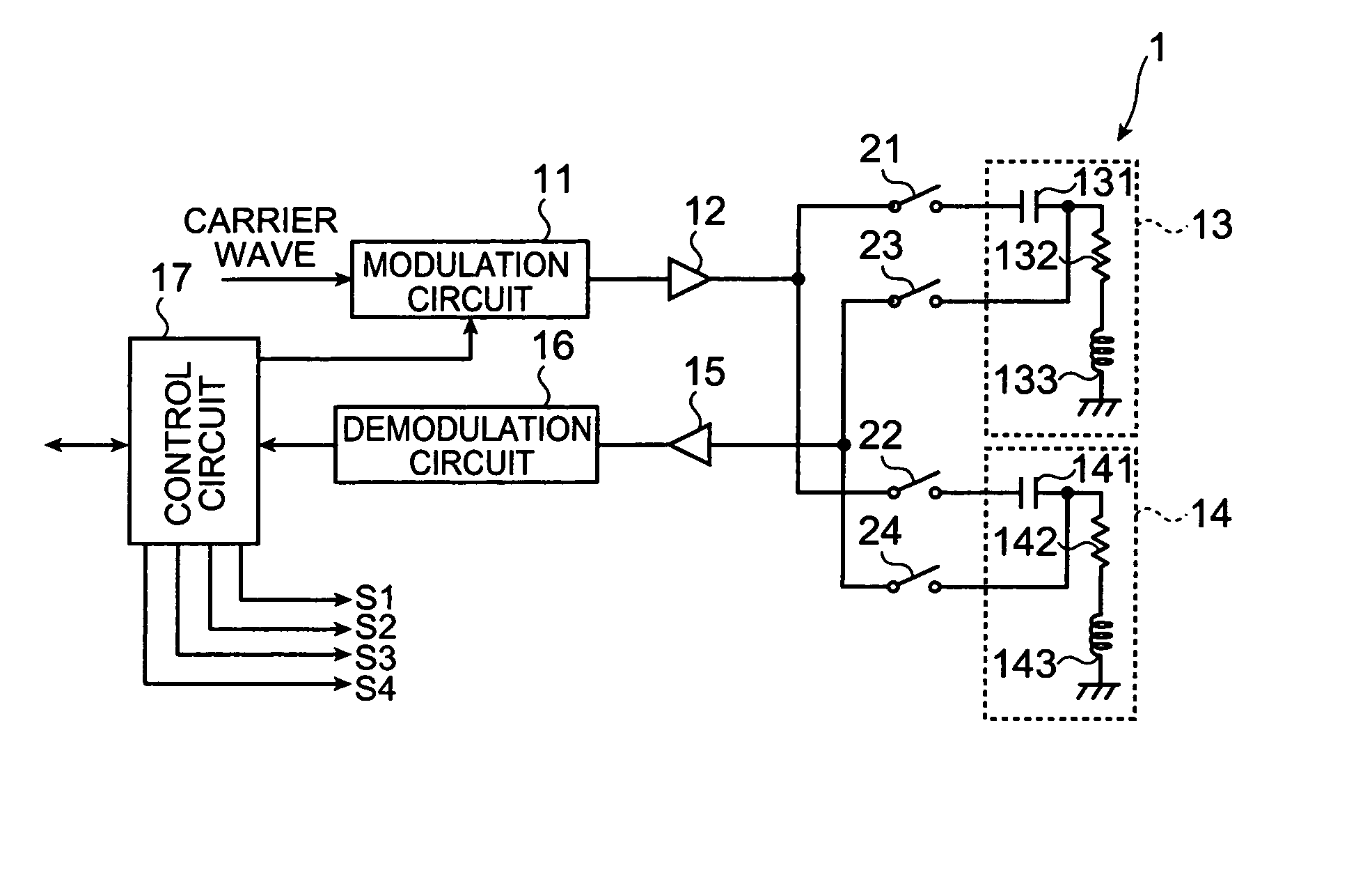
[0031]FIG. 1 is a circuit diagram showing a configuration of a reader / writer according to a first embodiment of the invention. A reader / writer 1 according to the first embodiment can perform a two-way communication with an unshown contactless tag through electromagnetic induction and can supply electric power to the contactless tag.

[0032]Accordingly, the reader / writer 1 has a modulation circuit 11, a power amplifier circuit 12, antenna circuits 13 and 14, an amplifier circuit 15, a demodulation circuit 16 and a control circuit 17 as shown in FIG. 1.

[0033]The reader / writer 1 further has switches 21, 22 between the power amplifier circuit 12 and the antenna circuits 13, 14, and switches 23, 24 between the amplifier circuit 15 and the antenna circuits 13, 14.

[0034]The modulation circuit 11 modulates a carrier wave from an oscillation circuit (not shown in the figure) according to send data outputted from the control circuit 17. The power amplifier circuit 12 amplifies the power of a mo...

second embodiment

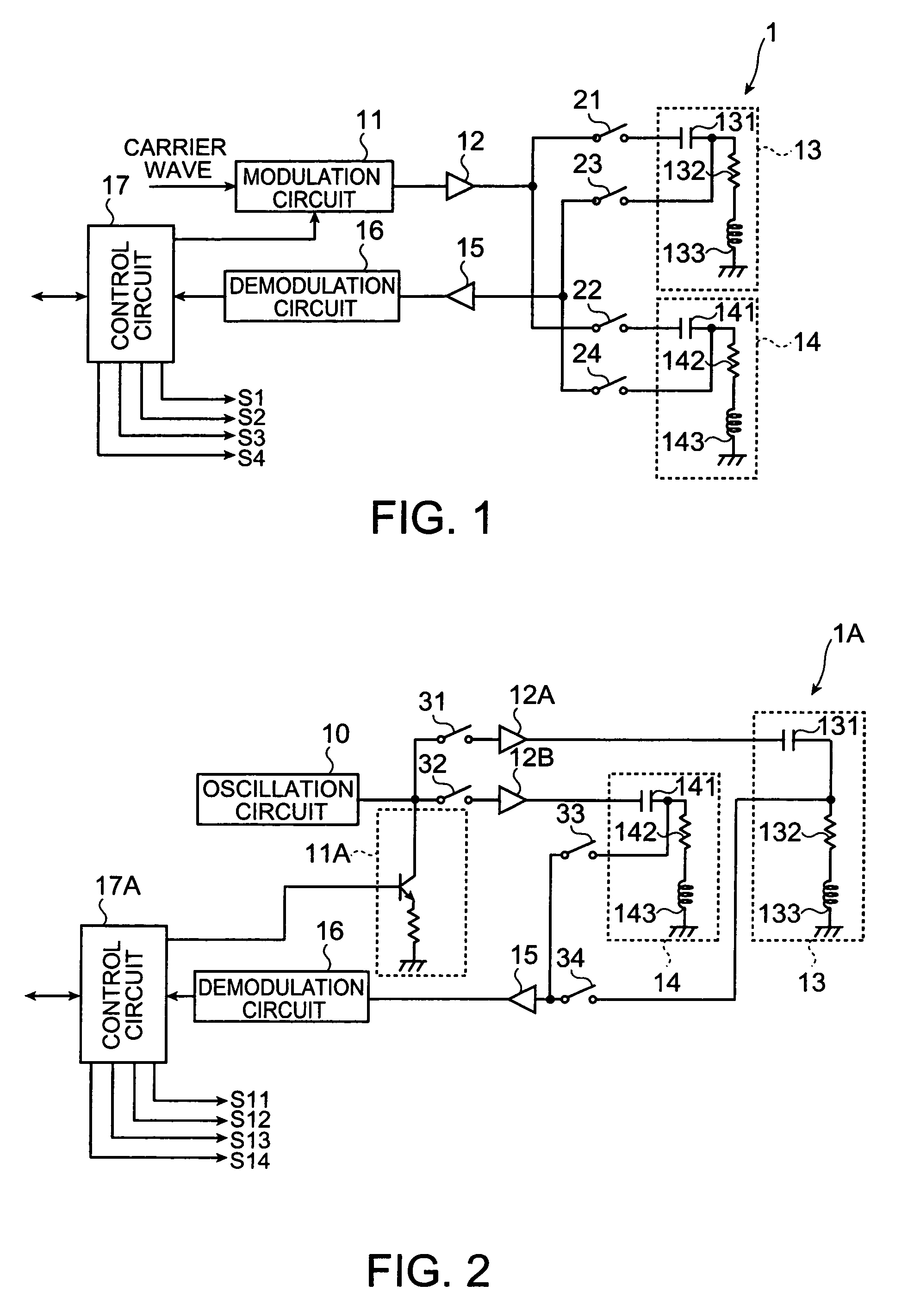
[0056]FIG. 2 is a circuit diagram showing a configuration of the reader / writer according to a second embodiment of the invention.

[0057]A reader / writer 1A according to the second embodiment can perform the two-way communication with an unshown contactless tag through the electromagnetic induction and can supply the electric power to the contactless tag.

[0058]Accordingly, the reader / writer 1A has an oscillation circuit 10, a modulation circuit 11A, power amplifier circuits 12A and 12B, the antenna circuits 13 and 14, the amplifier circuit 15, the demodulation circuit 16 and the control circuit 17A as shown in FIG. 2.

[0059]The reader / writer 1A further has switches 31, 32 correspondingly in the input sides of the power amplifier circuits 12A and 12B, and switches 33, 34 between the amplifier circuit 15 and the antenna circuits 13, 14.

[0060]The oscillation circuit 10 generates a carrier wave with a predetermined frequency. The modulation circuit 11A modulates the carrier wave from the os...

third embodiment

[0076]FIG. 5 is a circuit diagram showing a configuration of a reader / writer according to a third embodiment of the invention.

[0077]A reader / writer 1B according to the third embodiment can perform the two-way communication with an unshown contactless tag through the electromagnetic induction and can supply the electric power to the contactless tag.

[0078]Accordingly, the reader / writer 1B has the modulation circuit 11, the power amplifier circuit 12, matching circuits 51 and 52, antenna coils 53, 54, the amplifier circuit 15, the demodulation circuit 16 and the control circuit 17B as shown in FIG. 5.

[0079]The reader / writer 1B further has switches 61, 62 between the matching circuits 51 and 52 and the corresponding antenna coils 53, 54, and switches 63, 64 between the amplifier circuit 15 and the antenna coils 53, 54.

[0080]The modulation circuit 11 modulates the carrier wave from the oscillation circuit (not shown in the figure) according to a send data outputted from the control circu...


PUM


Abstract

An reader / writer performing a two-way communication with a contactless tag through electromagnetic induction and supplying electric power to the contactless tag, includes: an antenna circuit having an antenna coil for electromagnetically coupling with an antenna coil in the contactless tag, the antenna circuit provided in the plural number, a first amplifier circuit amplifying a signal which the antenna circuits send outside, a first switch provided between the first amplifier circuit and each antenna circuit, the first switch provided in the plural number, a second amplifier circuit amplifying a signal which the antenna circuit received, a second switch provided between the second amplifier circuit and each antenna circuit, the second switch provided in the plural number and a control circuit turning on a predetermined switch among the first switches and a predetermined switch among the second switches, wherein the antenna coil has a loop shape and a plurality of the antenna coils are provided adjacently each other in the same plane, and the loop of the antenna coil has a shape such that an adjoining region of the antenna coils becomes as small as possible.

Description

BACKGROUND[0001]1. Technical Field[0002]The present invention relates to a reader / writer forming a radio frequency identification (RFID) system.[0003]2. Related Art[0004]An RFID system including a contactless 1C card or a contactless tag such as an RF tag and a reader / writer has been known. Data and power are sent and received (two-way communication) between the tag and the reader / writer through electromagnetic induction.[0005]In such RFID system, the reader / writer can communicate with one or more than one contactless tag located near the reader / writer. However, it cannot efficiently communicate with the contactless tag located away from the reader / writer at the same time with the tag located near the reader / writer.[0006]JP-A-2000-36020 is an example of related art. In order to overcome such disadvantage, the example provides a plurality of antenna circuits for a transmission circuit of the reader / writer and switches between the transmission circuit and each of the plurality of the ...

Claims


Application Information

Patent Timeline
Patent Type & Authority Patents(United States)
IPC IPC(8): H04Q5/22
CPCG06K7/0008
Inventor YAMADA, TOSHIMICHI
Owner 138 EAST LCD ADVANCEMENTS LTD
Why Eureka
Try Eureka