Ophthalmoscopic stereomicroscope with correction component

a stereomicroscope and component technology, applied in the field of microscopes, can solve the problems of easy contamination, insufficient sterility of such supplementary optical systems, and disturbing the operation of surgeons,

Inactive Publication Date: 2008-09-09
LEICA INSTR SINGAPORE PTE
View PDF21 Cites 3 Cited by
  • Summary
  • Abstract
  • Description
  • Claims
  • Application Information

AI Technical Summary

Benefits of technology

[0009]Therefore, an object of the invention is to provide a microscope comprising a supplementary optical system, which especially allows for intraocular surgery, and which is provided in front of (preceding) the main objective, a contamination of said supplementary optical system during surgery being substantially avoidable, the supplementary optical system being of a small overall size, thus getting in the way of or disturbing the surgeon as little as possible. The beam paths within the microscope shall be as simple as possible.
[0010]This object is solved by a microscope according to the present invention. The microscope according to the invention is provided with a supplementary optical system comprising at least one lens disposed before (preceding) the main objective, and at least one component, especially at least one lens, which is disposed behind the main objective. By means of this positioning of a part of the supplementary optical system behind the main objective, i.e. on the observer's side in the microscope housing with respect to the main objective, a contamination of this part of the supplementary optical system during surgery may be effectively avoided. According to the invention, only the comparatively small ophthalmoscopical lens, which is very easy to clean, due to its (small) size, remains on the object side of the main objective. Thereby, the cleaning effort, especially during surgery, is reducible, as compared to conventional solutions. The microscope according to the invention is further characterised in that the optical axis of the magnification system disposed behind the main objective extends substantially perpendicularly to the optical axis of the main objective. With this measure, the vertical dimensioning of the microscope, and thus the ergonomical height can be minimised in an effective way.

Problems solved by technology

Since they are thus positioned outside the body of the microscope, they prove to be very disturbing for the operating surgeon, since they reduce the free working distance.
Further, such supplementary optical systems are very sensitive to dirt, so that the sterility of such supplementary optical systems, which are disposed in such a way, is insufficient.
There, it may be seen that a lens system designed as a BIOM-system (BIOM: Binocoular Indirect Ophthalmomicroscope) protrudes downwards into the operation area and, for this reason, may be easily contaminated by the activity of the surgeon.
Thereby, the lens, which is disposed close to the object (ophthalmoscopical lens), as well as the lens, which is disposed closer to the main objective (reduction lens) may be contaminated.
In case of time consuming surgery, both lenses of this preceding supplementary optical system must be cleaned in regular intervals, which proves cumbersome.
The arrangement of these two lenses or lens systems in one housing is considered to be cumbersome.
Also, such a housing proves to be disturbing for the surgeon in practical use.

Method used


Image

  • Ophthalmoscopic stereomicroscope with correction component
  • Ophthalmoscopic stereomicroscope with correction component
  • Ophthalmoscopic stereomicroscope with correction component

Examples


Embodiment Construction

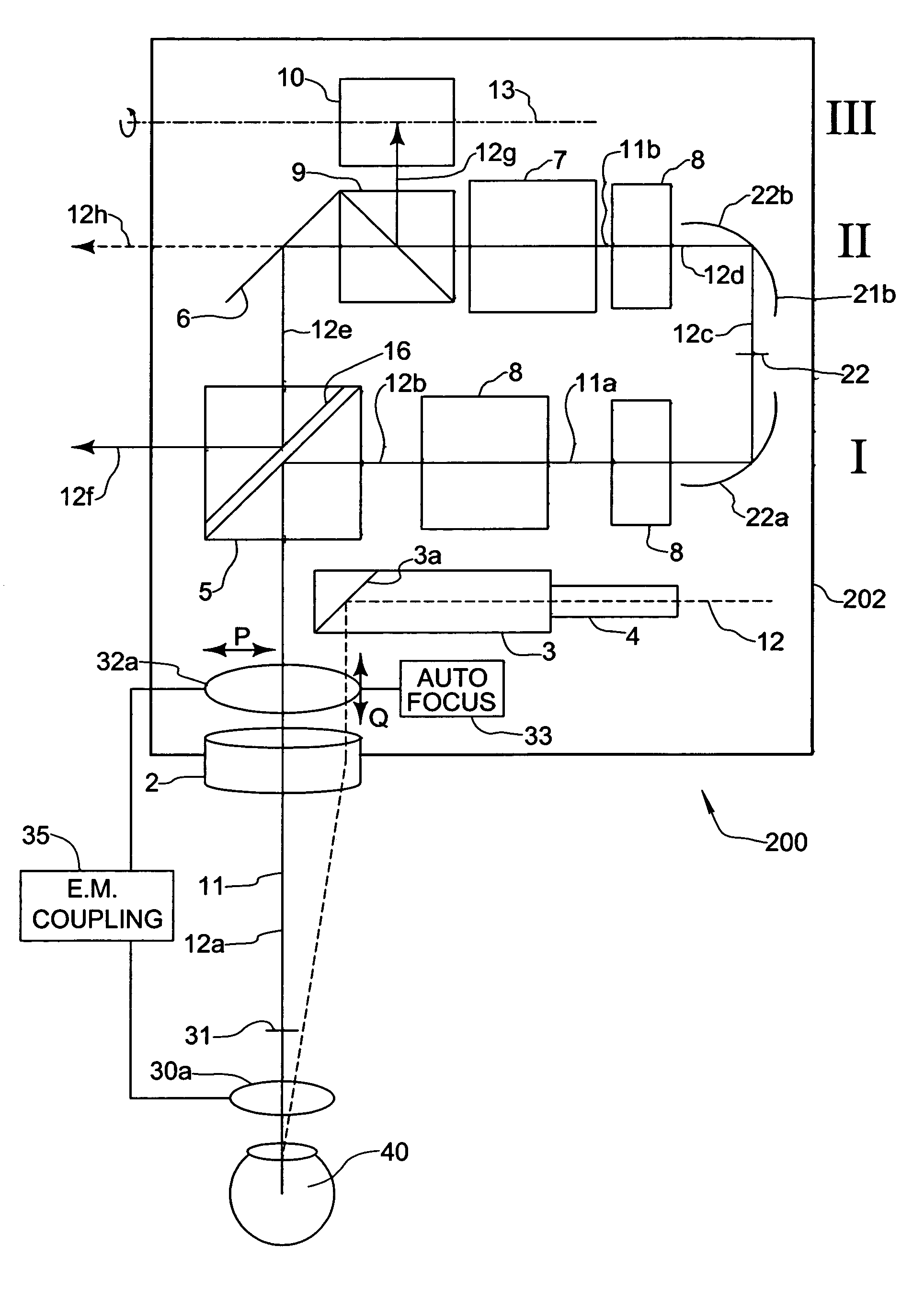
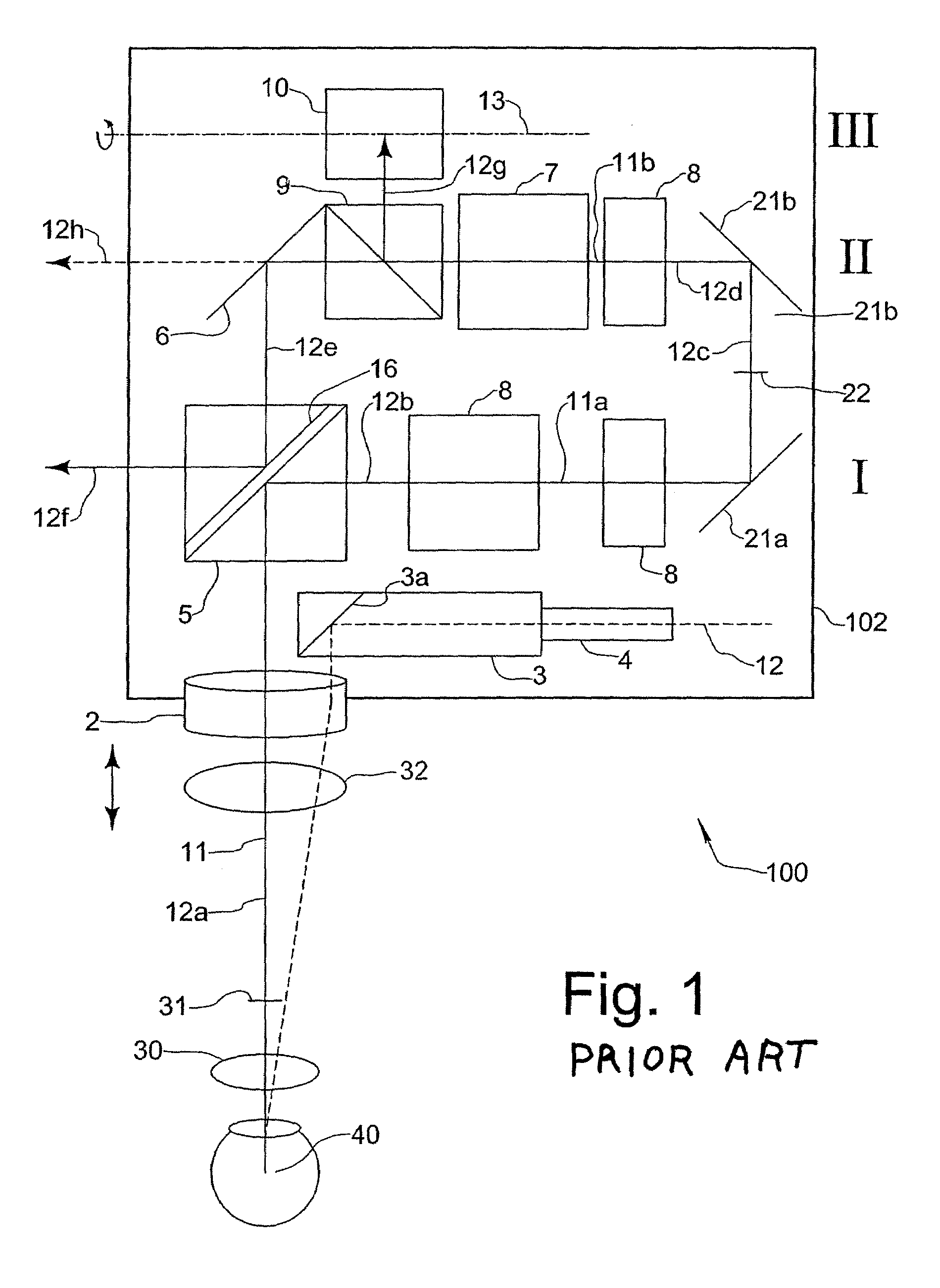
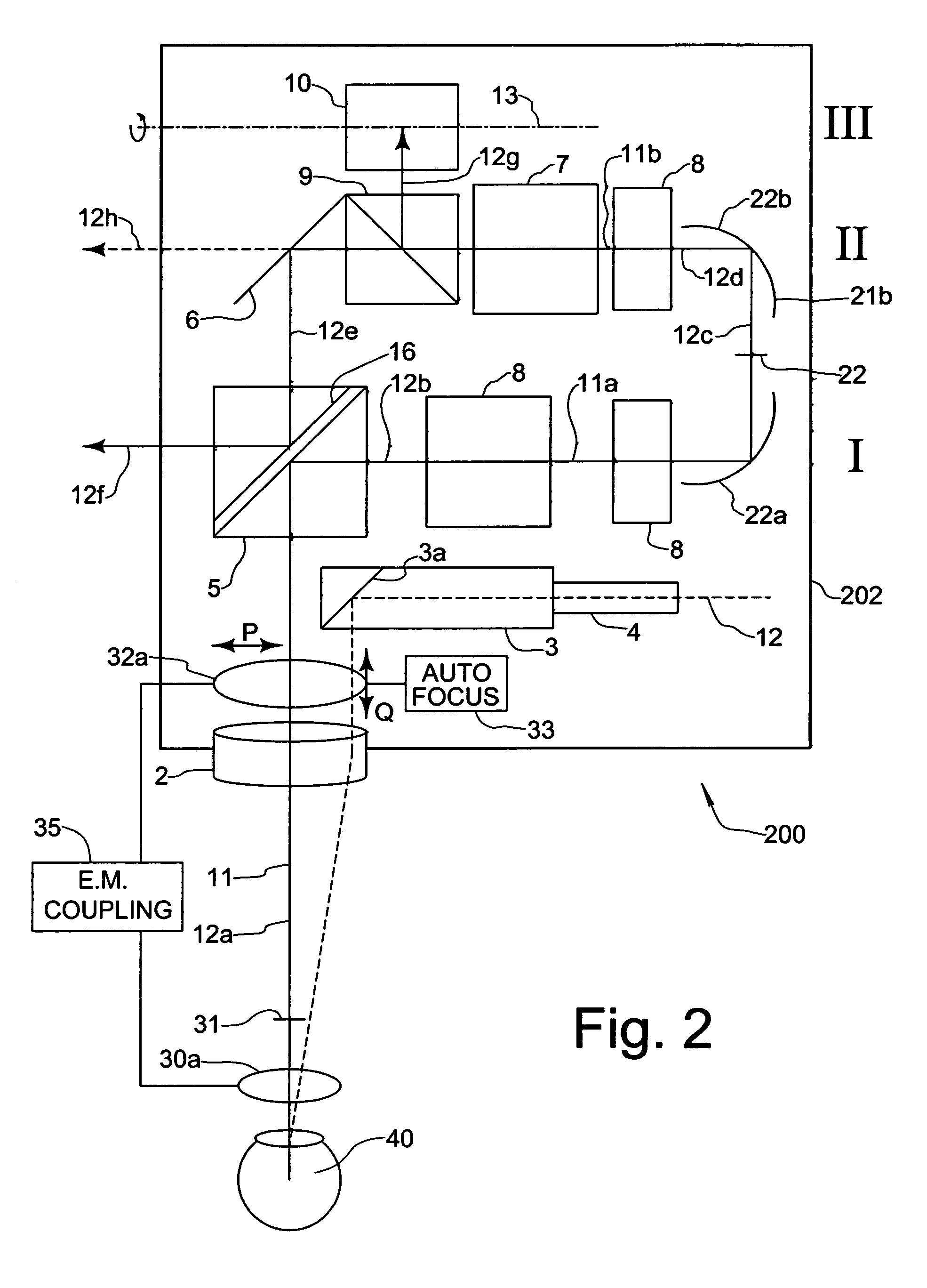
[0026]A stereoscopic microscope with a conventional supplementary optical system for carrying out intraocular surgery is referred to as a whole by reference numeral 100 in FIG. 1. The stereoscopic microscope has a microscope body 102, in which a main objective 2 and a magnification system 7, especially provided as a zoom-system, are disposed as main optical components.

[0027]The microscope 100 further comprises deflector elements 5, 21a, 21b provided as plane mirrors. By means of these deflector elements, viewing beams 12a-12h, which emerge from an object 40 to be inspected, and which at first proceed substantially (at 12a) in a vertical direction through the main objective 2 along the optical axis 11 thereof, are deflectable into two substantially horizontally extending planes I, II of the microscope (at 12b, 12d). It can be seen that the magnification system 7 in the shown embodiment is disposed in the second plane II.

[0028]At the object side of the magnification system 7, selectiv...


PUM


Abstract

Microscope, especially stereoscopic microscope, with a main objective (2), a magnification system (8, 7) disposed thereafter, and a supplementary optical system (30, 32a) for carrying out intraocular surgery, wherein the supplementary optical system comprises at least one ophthalmoscopic lens (30a) disposed before the main objective lens (2) and at least one optical component (32a) disposed behind the main objective lens (2) for providing a refraction and a focussing of a viewing beam path passing through the main objective (2), and the optical axis (12d) of the magnification system (7) disposed behind the main objective extending essentially perpendicularly to the optical axis (11) of the main objective (2).

Description

CROSS-REFERENCE TO RELATED APPLICATIONS[0001]The present application claims priority of German patent application numbers 103 32 603.0 and 103 32 602.2, both filed Jul. 17, 2003.FIELD OF THE INVENTION[0002]The present invention relates to microscopes, especially to stereoscopic microscopes of the type having a main objective, a magnification system disposed behind the main objective, and a supplementary optical system for carrying out intraocular surgery.BACKGROUND OF THE INVENTION[0003]Ophthalmological microscopes as such are known. They comprise a main objective, a magnification system disposed thereafter and a binocular system with eye-pieces (oculars). In order to provide a stereoscopic microscope, a splitting of a beam path passing through the main objective into a number of beam paths may be carried out in a magnification system, which may, for example, be provided as a zoom-system. Further, ophthalmological microscopes are known, which allow for a simultaneous viewing of an o...

Claims


Application Information

Patent Timeline
Patent Type & Authority Patents(United States)
IPC IPC(8): A61B3/13G02B21/00A61F9/007G02B21/22
CPCG02B21/22A61B3/13
Inventor SANDER, ULRICH
Owner LEICA INSTR SINGAPORE PTE
Why Eureka
Try Eureka