System and method for a transmission rate controller

a transmission rate and controller technology, applied in the field of network based communication, can solve the problems of buffer overflow, data loss (or drop), and the rate control mechanism standards known in the art are generally loss based

Active Publication Date: 2008-09-09
FLASH NETWORKS
View PDF20 Cites 196 Cited by
  • Summary
  • Abstract
  • Description
  • Claims
  • Application Information

AI Technical Summary

Benefits of technology

[0006]There is provided, in accordance with an embodiment of the present invention, a method for controlling the transmission rate of data between stations. The method may include calculating a latency value per packet of a plurality of packets and generating at least one rate change from the one latency value.

Problems solved by technology

If too much data is sent to the queue, the buffer will overflow and data will be lost (or dropped).
Unfortunately, the rate control mechanism standards known in the art are generally loss based.
Users of data communication networks often experience severe communication constraints due to non-optimal handling of the data transmission.
This may be due to an inefficient use of the network bandwidth and a rate of data transmittal slower than necessary.
Contributing to these are the inherent inefficiencies of existing communication protocol standards and the current explosion of network traffic, which is overloading the capacity of networks.

Method used


Image

  • System and method for a transmission rate controller
  • System and method for a transmission rate controller
  • System and method for a transmission rate controller

Examples


Embodiment Construction

[0050]The present invention is a system and method to control data transmission rates. The present invention may comprise an improved system and method for maximizing bandwidth use while minimizing data loss. The present invention may allow the use of independent clocks on the receiving and transmission stations without the requiring the synchronization of the clocks. The transmission rate control system and method of the present invention may be used for connection based and connectionless communication.

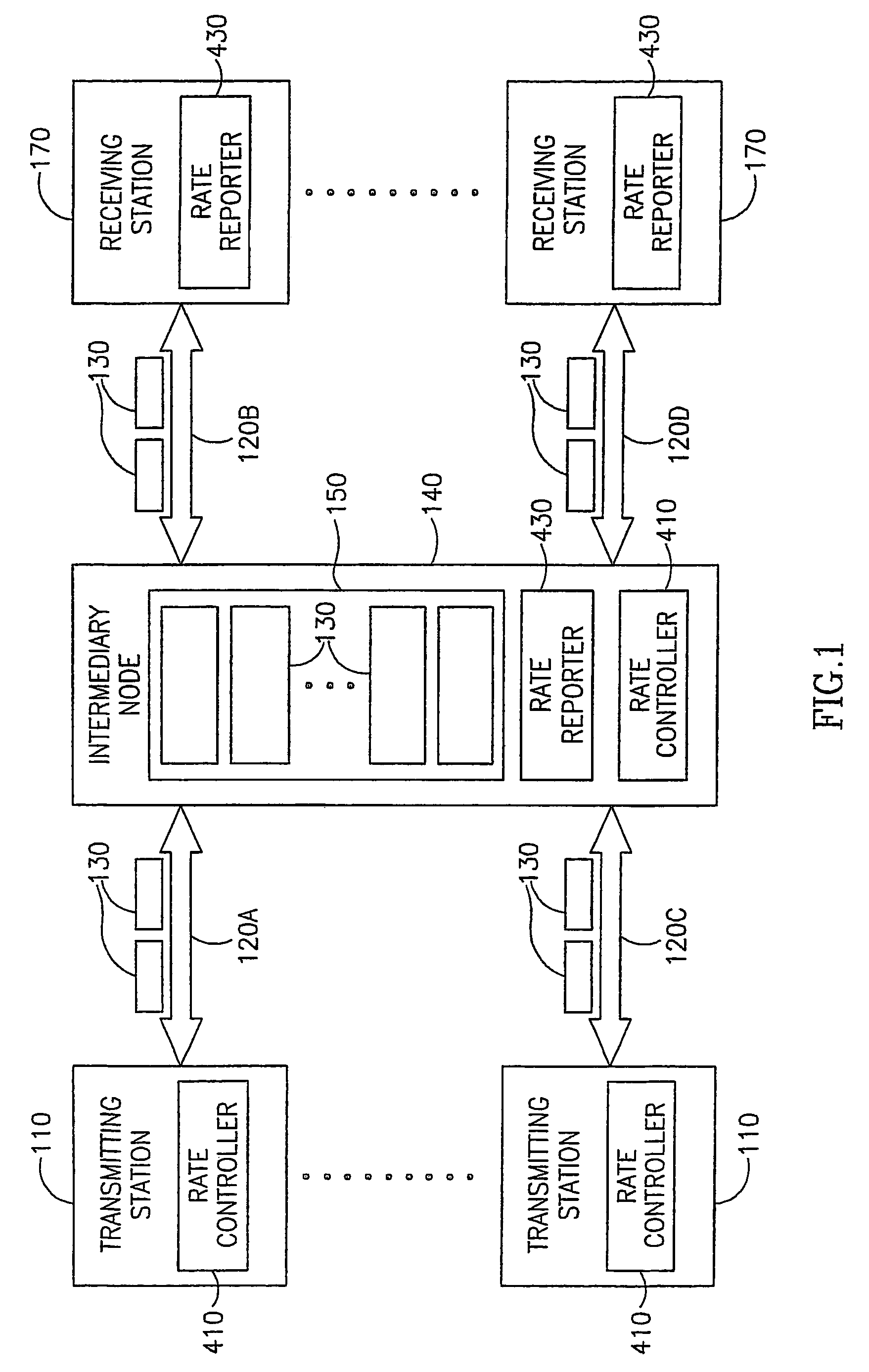
[0051]FIG. 1, to which reference is now made, is a block diagram illustration of a communication environment, which may comprise a transmission rate control system that is operative in accordance with an embodiment of the present invention. The communication system may comprise at least one transmitting station 110, at least one communication line 120, optional intermediary nodes 140, and at least one receiving station 170. The rate controlled transmission system may be comprised of...


PUM


Abstract

A method for proposing at least one transmission rate change including calculating a plurality of latency values, computing at least one derivative-based proposed change from the plurality of latency values, and proposing a rate change selected from the at least one derivative-based proposed change. Also provided is a system including a rate controller controlling the transmission rate of data between two stations over a network and a rate reporter in communication with the rate controller.

Description

FIELD OF THE INVENTION[0001]The present invention relates generally to network based communication, specifically to improvements in bandwidth use.BACKGROUND OF THE INVENTION[0002]Data communication networks are built from various communication lines connected to each other. Every communication line has a specific capacity (or bandwidth), generally measured in units of data per time, typically kilobits per second (kbps). When data is transmitted over a communication line by some station in the network, hereinbelow referred to as the sitting station, it is transmitted at the specific transmission rate of that communication line. Between the transmitting station and the communication line there is usually a queue of limited size, in which data waits to be sent if the line is occupied. If a station attempts to transmit data faster than the capacity of the line, the excess data is stored in the queue until it can be sent. If too much data is sent to the queue, the buffer will overflow an...

Claims


Application Information

Patent Timeline
Patent Type & Authority Patents(United States)
IPC IPC(8): H04L12/00H04J3/14H04L1/00H04L12/56
CPCH04L1/0002H04L1/0018H04L1/0026Y02B60/31H04L2001/0097Y02D30/50
Inventor SHAHAM, ODEDSAGIV, AVISHAPIRA, YAIRZAKAI, NOAM
Owner FLASH NETWORKS
Why Eureka
Try Eureka