Fuel injection control apparatus for internal combustion engine

a control apparatus and fuel injection technology, applied in the direction of electric control, machines/engines, liquid fuel feeders, etc., can solve the problems of large errors and moderate change in the fuel injection rate after the start of the fuel injection, and achieve the effect of improving accuracy

Active Publication Date: 2006-02-21
TOYOTA JIDOSHA KK
View PDF14 Cites 34 Cited by
  • Summary
  • Abstract
  • Description
  • Claims
  • Application Information

AI Technical Summary

Benefits of technology

[0017]The present invention has been made in view of the above-described situation. An object of the present invention is to provide

Problems solved by technology

In addition, when the rail pressure is low, the change in the fuel injection rate after the start of the fuel injection is moderate.
Thus, in the case that the rail pressure is low, influence of the value (A–B) is significant,

Method used


Image

  • Fuel injection control apparatus for internal combustion engine
  • Fuel injection control apparatus for internal combustion engine
  • Fuel injection control apparatus for internal combustion engine

Examples


embodiment 1

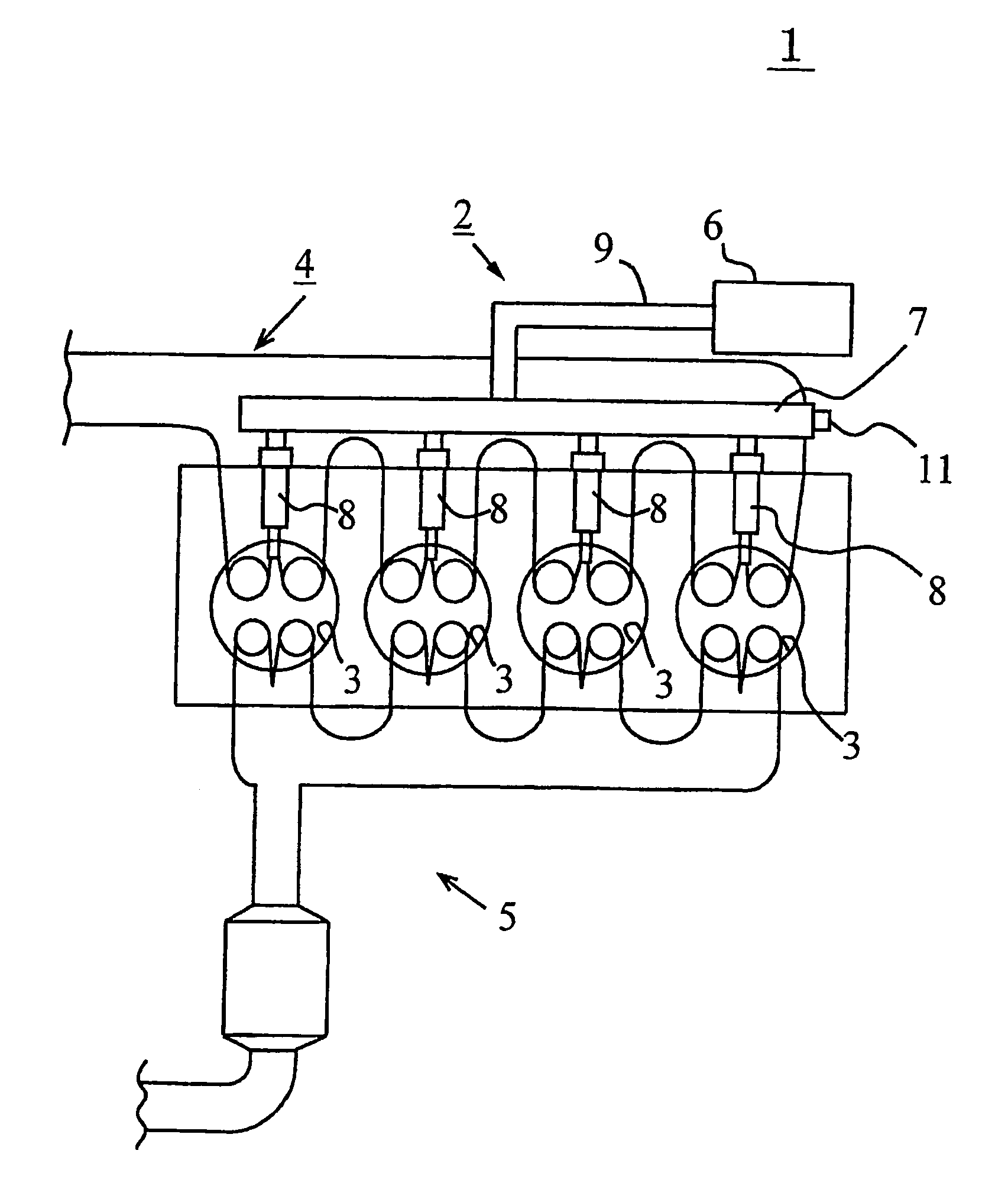
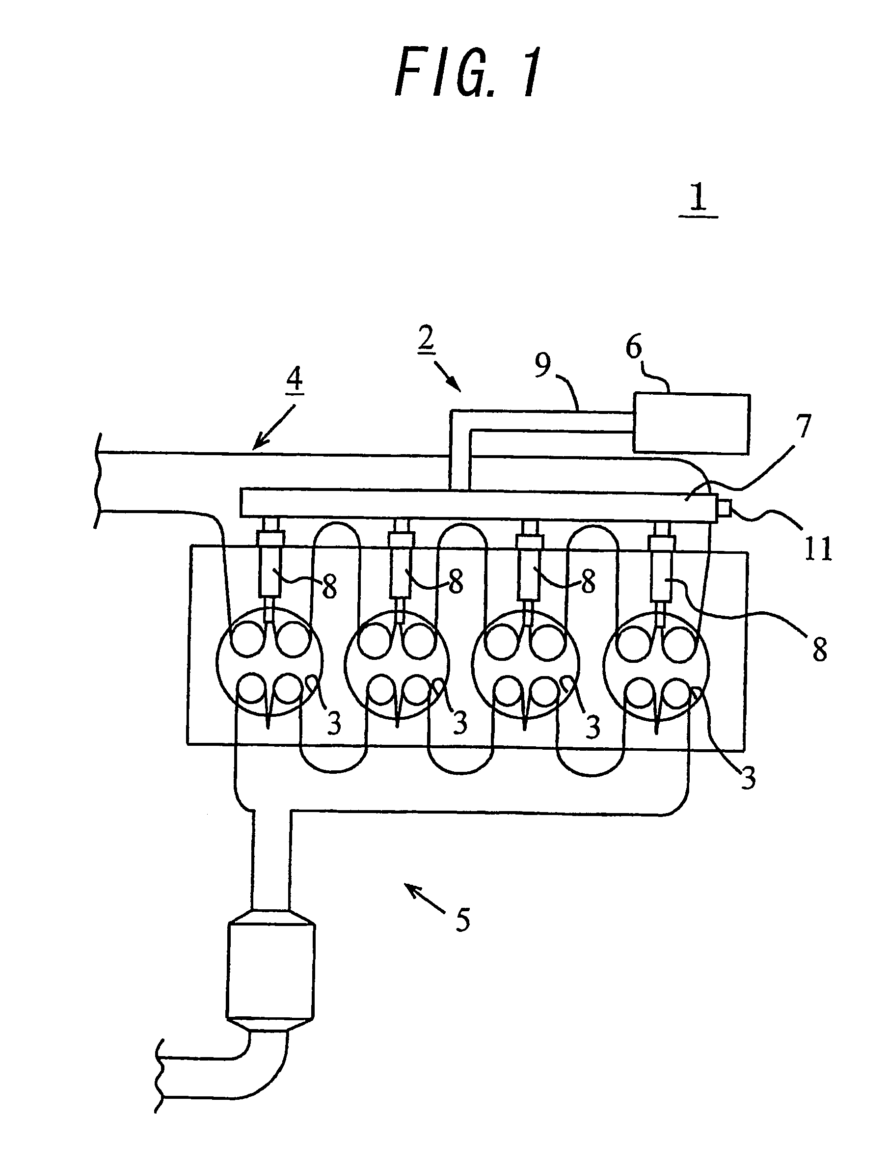
[0071]FIG. 1 schematically shows the basic structure of a diesel engine as an internal combustion engine in which a fuel injection control apparatus according to a first embodiment of the present invention is applied.

[0072]As shown in FIG. 1, the internal combustion engine 1 is mainly composed of a fuel supply system 2, cylinders (or combustion chambers) 3, intake passage 4 and exhaust passage 5. The internal combustion engine 1 is an in-line four cylinder diesel engine in which four cycles including intake stroke, compression stroke, explosion stroke (or expansion stroke) and exhaust stroke are repeated to create an output.

[0073]The fuel supply system 2 includes a supply pump 6, a common rail 7, fuel injection valves 8, fuel passage 9 etc. The supply pump 6 raises the pressure of the fuel drawn from a fuel tank (not shown) to a high pressure and supplies the fuel to the common rail 7 through the fuel passage 9. The common rail 7 functions as a pressure accumulation chamber for main...

embodiment 2

[0143]In the second embodiment of the present invention, in the case that execution of the fuel injection is completed before the lift amount of the needle valve 23 reaches the full lift, the fuel injection quantity is corrected in accordance with a method different from the method described in connection with the first embodiment. FIG. 10 is a block diagram showing the fuel injection quantity variation calculation means 57 and related portions in this embodiment. In this embodiment, the ECU 10 constitutes the suction chamber pressure calculation means 57a and the unit fuel injection quantity variation calculation means 57b.

[0144]The fuel injection quantity variation calculation means 57 is equipped with a suction chamber pressure calculation means 57a for calculating pressure in a suction chamber 26 formed in the tip end side of a valve seat on / from which the needle valve 23 is to be received / detached, based on the fuel pressure detected by the rail pressure sensor 11 and the posi...

embodiment 3

[0151]In the third embodiment of the present invention, correction of the fuel injection quantity is performed based on the rail pressure Pcr and the in-cylinder pressure of the engine Pcl, unlike with the first embodiment. Specifically, when the in-cylinder pressure of the engine Pcl increases, it is assumed that the rail pressure Pcr has decreased, and fuel injection time is calculated while compensating the variation in the fuel injection quantity due to a change in the fuel injection rate based on the difference between the rail pressure Pcr and the in-cylinder pressure of the engine Pcl. In addition, when the in-cylinder pressure of the engine Pcl increases, it is assumed that the rail pressure Pcr has increased, and variation in fuel injection start time is calculated based on the sum of the rail pressure Pcr and the in-cylinder pressure of the engine Pcl.

[0152]FIG. 11 is a block diagram of the fuel injection control apparatus in this embodiment.

[0153]As shown in FIG. 11, the ...


PUM


Abstract

In controlling power supply time, a variation in the fuel injection quantity caused by a variation in the fuel injection rate at the in-cylinder pressure of the engine (detected or estimated value in the running state of the internal combustion engine) relative to the fuel injection rate at a reference in-cylinder pressure (under the condition of an injector characteristic measuring benchmark test), and in addition, a variation in the fuel injection start time is corrected. In the calculation of the variation in the fuel injection quantity, a fuel injection rate changing behavior model in which changing behavior of the fuel injection rate is modeled as a trapezoid is used to calculate the areas of Δq1 and Δq2. The variation in the fuel injection start time Δτd is calculated based on the rail pressure and the variation in the in-cylinder pressure. In this way, there is provided a technology for controlling the fuel injection quantity that changes with a change in the in-cylinder pressure with improved accuracy.

Description

TECHNICAL FIELD[0001]The present invention relates to a fuel injection control apparatus for an internal combustion engine.BACKGROUND ARTS[0002]Conventionally, among direct injection internal combustion engines having a fuel injection valve (or an injector) for injecting fuel directly into the interior of the cylinder, one having a function of correcting the opening time of the fuel injection valve based on the pressure in the interior of the cylinder (or the in-cylinder pressure) is known (see, for example, patent document 1 listed later).[0003]The reason why this function is adopted is that the pressure in the interior of the cylinder (the in-cylinder pressure) acts as a back pressure against the fuel injection valve. In this function, the in-cylinder pressure that changes in accordance with the running condition of the engine is calculated to correct the opening time of the fuel injection valve, thereby obtaining a desired fuel injection quantity.[0004]However, in the above-descr...

Claims


Application Information

Patent Timeline
IPC IPC(8): F02M37/04F02D35/02F02D41/40F02M47/00F02D45/00F02M51/00
CPCF02D35/02F02D41/40Y02T10/44F02D2041/1433F02D35/023F02D35/024Y02T10/40
Inventor YAMADA, TAKAFUMIWATANABE, YOSHIMASA
Owner TOYOTA JIDOSHA KK
Why Eureka
Try Eureka