Hydraulic transformer

A hydraulic transformer and distribution plate technology, applied in the field of hydraulic transformers, can solve problems such as hydraulic transformer size reduction, increase in hydraulic transformer complexity, oil energy loss, etc., to expand the range of voltage regulation ratio and solve oil throttling loss , Noise reduction effect

Inactive Publication Date: 2003-11-12
ZHEJIANG UNIV
View PDF0 Cites 31 Cited by
  • Summary
  • Abstract
  • Description
  • Claims
  • Application Information

AI Technical Summary

Problems solved by technology

In this patent, the high-pressure port on the front end of the distribution plate is led to the center of the rear end of the distribution plate, the positions of the other two slots remain unchanged, and the slots of the rear end cover are also adjusted accordingly. The turndown ratio range has been improved, but is still very limited, and there is an energy loss in the oil between the rear end cover and the valve plate
In this patent, the four notches of the rear end cover are respectively connected to the two load oil circuits and the low-pressure oil circuit through the reversing valve, which increases the complexity of the hydraulic transformer structure
At the same time, in this patent, in order to prevent the inclination of the valve plate, a rolling bearing with a large radial dimension is used, which increases the volume of the hydraulic transformer
[0011] In Endsley, John, c.Hydraulic pressure transformer. WO 00 / 28211, 18 May 2000 patent, it is proposed to replace the valve plate and the rolling bearing with the valve plate block of the static pressure support structure, so that the size of the hydraulic transformer is reduced. In this In the structural hydraulic transformer, a plate needs to be sealed and connected with the thick end cover through threads first, and then the rear broken cover is connected with the shell, which increases the complexity of the hydraulic transformer

Method used


Image

  • Hydraulic transformer
  • Hydraulic transformer
  • Hydraulic transformer

Examples


Embodiment Construction

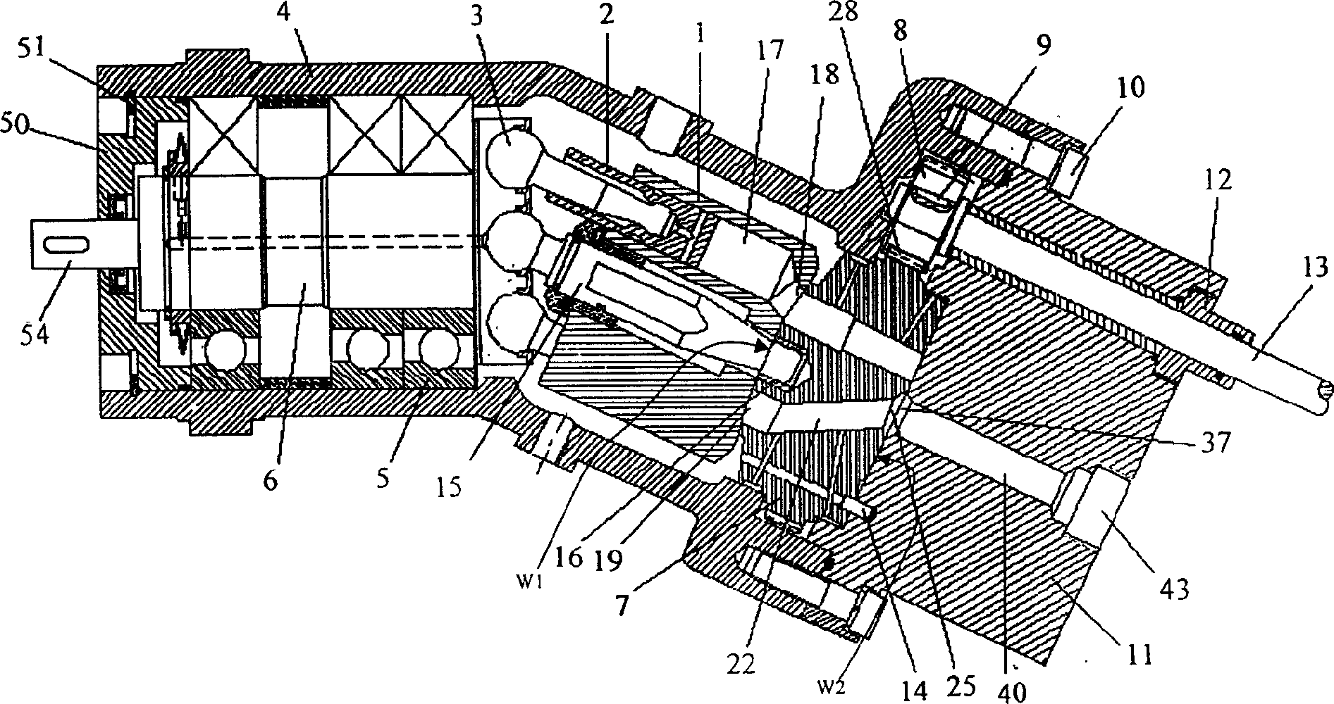
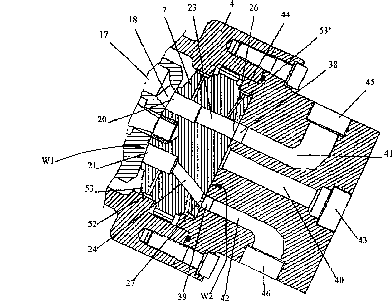
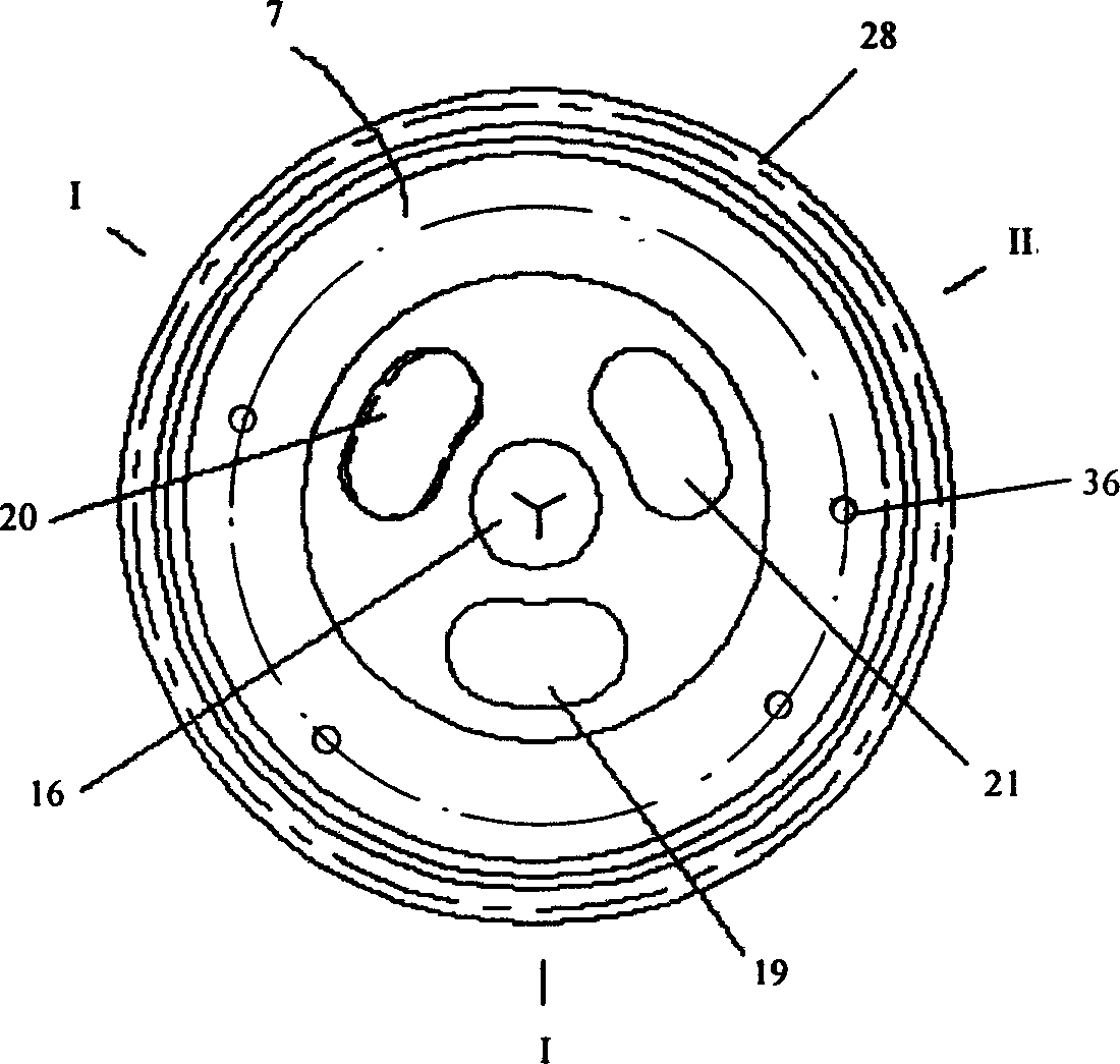
[0031] Such as Figure 1 to Figure 9 As shown, the present invention includes:

[0032]1) One end of the inclined-axis type casing 4 is connected to the rear end cover 11, and the other end of the inclined-axis type casing 4 is connected to the front end cover 50 to form a closed cavity of the inclined-axis type hydraulic transformer, which is mounted on the inclined-axis One end of the rotating shaft 6 in the type housing 4 is connected to the output end 54 installed on the front end cover 50, the axis of the central shaft 15 intersects the axis of the rotating shaft 6, and the flow plate 7 is mounted on the cylinder body 1 and the rear end cover 11 Between; one end of the central shaft 15 on the cylinder body 1 is hinged on one end of the rotating shaft 6, and the other end of the central shaft 15 is installed at the elongated hole 16 in the center of the front end of the distribution plate, and the cylinder body 1 is equipped with a plunger 2, The plunger 2 is connected wi...


PUM


Abstract

The present invention discloses a hydraulic pressure changer, formed from shell, front end cover, rotating shaft, plunger, cylinder, port plate and rear end cover. According to the working principle of hydraulic pressure changer it utilizes the control of rotating angle of port plate of said hydraulic pressure change, regulation of flow rate change of three oil holes of the pressure changer and further control of output pressure of the pressure changer to drive lienar load or rotary load to make it move. By adopting special port plate and rear end cover structure said invention can resolve the oil liquor throttling loss between the port plate and rear end cover, exaggerate the pressure-regulating ratio range of hydraulic pressure changer and can make it implement the functions of regulating pressure.

Description

technical field [0001] The invention relates to hydraulic components, in particular to a hydraulic transformer. Background technique [0002] The constant pressure network secondary regulation technology developed in recent years has improved the flexibility and efficiency of the hydraulic system. However, although there are many advantages in the principle of secondary regulation, its application in the hydraulic field has been limited to a certain extent. In terms of driving the rotating load, the driving of the rotating load can be realized by adjusting the adjustment mechanism of the variable hydraulic motor. The traditional method of driving linear loads with different load pressure requirements is through a throttling control method. Since the throttling control method has a large pressure difference, this control method brings a large energy loss. How to transmit the energy of the constant voltage network with a certain pressure without ene...

Claims


Application Information

Patent Timeline
Patent Type & Authority Applications(China)
IPC IPC(8): F04B1/20F15B3/00
Inventor 徐兵欧阳小平杨华勇
Owner ZHEJIANG UNIV
Why Eureka
Try Eureka