
Telescopically moving structure

a technology of moving structure and rotating shaft, which is applied in the direction of rod connection, variable height table, gearing, etc., can solve the problems of splined shafts of small diameters that cannot transfer high torque and the driving mechanism can easily be damaged, and achieve the largest possible stability of the structure

Inactive Publication Date: 2008-09-16
IDE ASSOCS (IOM) LTD
View PDF4 Cites 25 Cited by
  • Summary
  • Abstract
  • Description
  • Claims
  • Application Information

AI Technical Summary

Benefits of technology

[0012]It is an object of the present invention to provide a telescopically moving structure of the above mentioned type, which is able to work even against a strong force, i.e. is able to transfer a large torque.
[0013]The telescopically moving structure according to the invention is characterized in that the driving shaft has an essentially polygonal cross section with a perimeter forming two opposite longitudinal tracks for engagement with torque-transferring rolling bodies which are journalled in a bushing fastened in the spindle tube. With transfer of the torque from the driving shaft to a bushing inserted in the spindle tube by means of opposite longitudinal tracks for engagement with torque-transferring rolling bodies, the axial friction will be minimized, and the structure can therefore be used for movement of relatively heavy objects without risk of seizure.
[0015]An alternative embodiment of the telescopically moving structure according to the invention is characterized in that the driving shaft is designed as a polygonal tube freely surrounding the spindle tube, and where said tracks are formed by corners between internal adjacent sides. This design of the driving shaft enables transfer of a large torque as the diameter of the diving shaft is considerably enlarged, the force necessary to rotate the spindle therefor being considerably reduced. The tubular driving shaft can thus be designed with relatively thin walls, and the rollers and their bearings will be correspondingly simplified.
[0016]A further embodiment of the telescopically moving structure is characterized in that the rolling bodies are provided by ball or roller bearings, preferably deep groove ball bearings, which assure both a low friction and a sufficient wearing resistance.
[0018]The main parts making up the telescopically moving structure, i.e. the spindle tube, the spindle and nuts may be ordinary threaded parts, but preferably one or more of these parts are produced by hydroforming i.e. deforming a tube in a mould by a fluid under pressure. An actuator using elements manufactured by hydroforming is disclosed in WO 98 / 25051 A1. Although the cost of a device for manufacturing the parts by hydroforming is very high, this method is very cost effective when large quantities are produced as the cost per unit is very low compared to ordinary threaded spindles. Further the wave-shape of the walls forming rounded tracks or threads producible by hydroforming is very well suited for transfer of large torques without risk of jamming of the parts, so spindles having a high pitch can be used. This means that the structure can be driven from retracted to extended state in very few revolutions of the driving shaft, so noise related hereto and wear of the spindles will be minimized. With hydroforming it is possible to produce a telescopically, moving structure of very small diameter as with this manufacturing process it is possible to produce spindles having a very small the thickness of the walls without sacrifice of strength. In fact a spindle having a 10 mm diameter and a wall thickness of 1 mm will be stronger than a corresponding massive rod because of the shape of the wall, i.e. corrugations or rounded tracks in the wall. Still a further advantage is that it is possible to produce spindles having changing cross section along the length, for example having integral “nuts” in the end of the spindle and / or formed with longitudinal tracks for rollers.
[0020]Furthermore, the invention has the advantage that the even telescoping of the elements assures the largest possible stability of the structure in a partially telescoped condition, all elements being inserted approximately evenly in its adjacent element or elements.

Problems solved by technology

If, for example, a height-adjustable table during transport or the like is dropped from a few centimeters, the driving mechanism can easily be damaged, if this axial force is transmitted to gear wheels or the like.
A disadvantage of this actuator is that the spindle tube is driven by a small diameter splined shaft, which will not be able to transfer high torque because this may result in seizure so the splined shaft cannot slide in the splined hole.
A disadvantage of this actuator is that a splined shaft of small diameter will not be able to transfer high torque, because this may result in seizure so the splined shaft cannot slide in the splined hole.
A disadvantage of this construction is that it is rather complicated and has large dimensions, so it is not suitable for being used as a telescopically moving structure in general, and further the drive means is not slidably connected to the spindle.

Method used


Image

  • Telescopically moving structure
  • Telescopically moving structure
  • Telescopically moving structure

Examples


Embodiment Construction

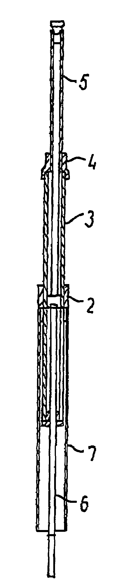
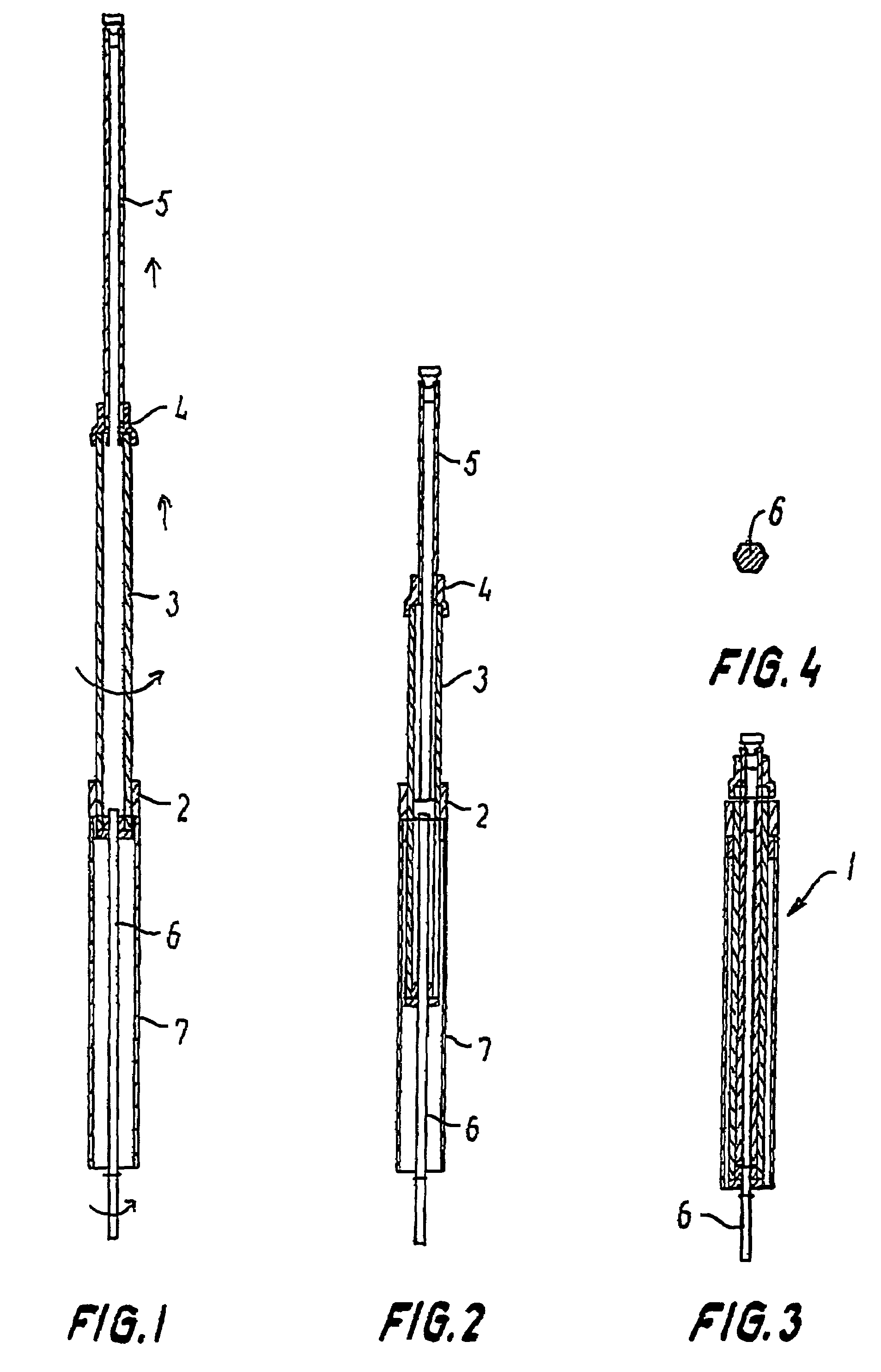
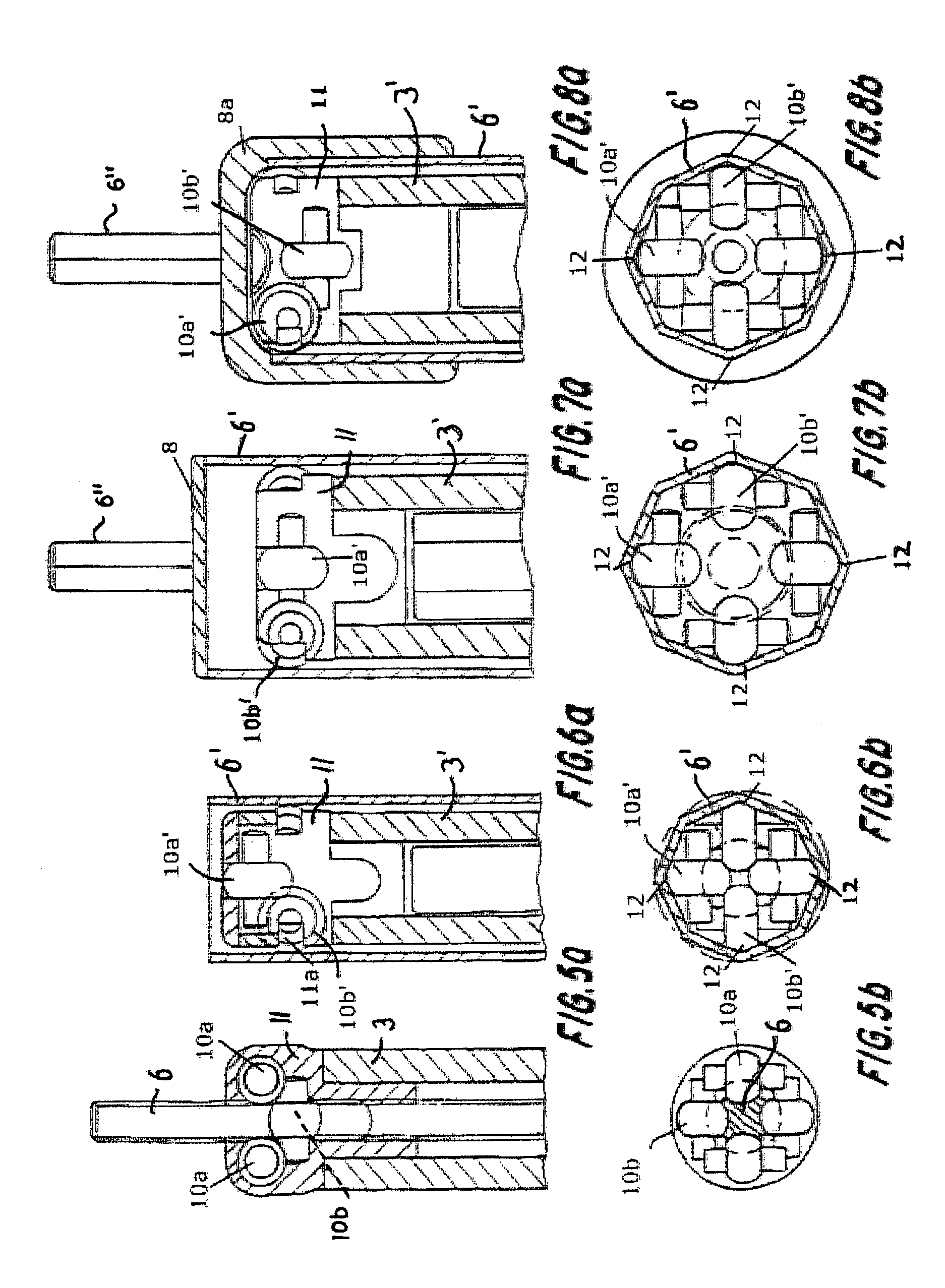
[0031]The telescopically moving structure 1 comprises a spindle tube 3 with an external thread engaging a nut 2 mounted in a rotationally fixed manner. The spindle tube 3 can be turned with respect to the nut 2 by means of a drive shaft 6 connected with one end of the spindle tube 3 to be rotationally fixed with respect to the spindle tube, while allowing slidable displacement thereof in the axial direction. Thus, by rotation of the drive shaft 6 the spindle tube 3 will move linearly in the axial direction with respect to the nut 2. The spindle tube 3 is further provided with an internal thread 4 of opposite direction of inclination to that of the external thread, said internal thread 4 being engaged by a corresponding external thread on a non-rotating spindle 5 such that at the rotation of the spindle tube 3 the spindle 5 is displaced in the same axial direction as the spindle tube 3. The internal thread 4 can as shown be provided by a collar or nut mounted in a rotationally fixed ...


PUM


Abstract

A telescopically moving structure (1) comprising a nut (2) mounted in a rotationally fixed manner in relation to a frame part, a spindle tube (3) with an external thread in engagement with the nut (2), which spindle tube (3) furthermore has an internal thread (4) with the opposite direction to that of the external thread, which internal thread (4) is in engagement with a non-rotational spindle (5) provided with an external thread, the spindle tube (3) being connected in a rotationally fixed manner, but in the axial direction in a slidable manner to a driving shaft (6), wherein the driving shaft (6) has an essentially polygonal cross section with a perimeter forming two opposite longitudinal tracks for engagement with torque-transferring rolling bodies which are journalled in a bushing fastened in the spindle tube (3) to thereby enable transfer of a large torque without the risk of seizure between the driving shaft (6) and the spindle tube (3).

Description

BACKGROUND OF THE INVENTION[0001]1. Technical Field of the Invention[0002]The present invention relates to a telescopically moving structure comprising a nut mounted in a rotationally fixed manner in relation to a frame part, a spindle tube with an eternal thread in engagement with the nut, which spindle tube furthermore has an internal thread with the opposite direction to that of the external thread, which internal thread is in engagement with a non-rotational spindle provided with an external thread, the spindle tube being connected in a rotationally fixed manner, but in the axial direction in a slidable manner to a driving shaft.[0003]2. Prior Art[0004]Telescopically moving structures of this kind have an increasing importance as demands for compact and versatile telescopic structures are growing. Structures of said kind can, as will appear later, be telescoped to essentially the triple length, which makes them very suitable for e.g. height-adjustment of tables, however, they ar...

Claims


Application Information

Patent Timeline
Patent Type & Authority Patents(United States)
IPC IPC(8): F16H25/22A47B9/04F16B7/14F16H25/20
CPCA47B9/04F16B7/1436F16H25/2056F16H25/20Y10T74/18576Y10T74/18672
Inventor FICH, PREBEN BONOERGAARD, CHRISTIAN
Owner IDE ASSOCS (IOM) LTD
Learn More