
Method and device for calculating an iterated state for a feedback shift register arrangement

a technology of feedback shift and register arrangement, applied in the field of method and device for calculating an iterated state of a feedback shift register arrangement, can solve the problems of increasing the difficulty of controlling the overall time sequence, increasing the computational complexity and the amount of time required, and inacceptable delay in transmission and reception, so as to save memory space

Inactive Publication Date: 2008-09-16
INFINEON TECH AG
View PDF10 Cites 10 Cited by
  • Summary
  • Abstract
  • Description
  • Claims
  • Application Information

AI Technical Summary

Benefits of technology

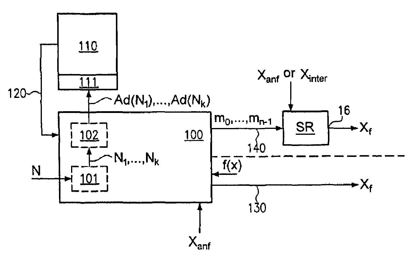
[0017]The invention is thus based on the insight that a state, developed further by N′ iterations, for the shift register arrangement can be calculated or generated by determining a suitable tap mask for the shift register arrangement and subsequently performing n shift register operations. If N=N′, which is particularly preferable, then the final state sought is obtained, from the initial state, almost entirely (apart from the remaining n shift register operations) through the explicit calculation of the tap mask for N. In comparison with the prior art, in which the final state is obtained through N-fold iteration of the shift register arrangement, the advantage of the invention is that it is possible to determine the tap mask in a much shorter time than carrying out N prior iterations (it is pointed out that N is very large in many fields of application).
[0018]This advantage is fundamentally retained when N′<N, i.e. a state change in the shift register arrangement for just a share N′ of the required N iterations is calculated by calculating the associated tap mask and subsequently carrying out n shift register operations. The remaining N-N′ iterations of the shift register arrangement can then be carried out before or after or both partly before and partly after the inventive calculation of an N′-fold iterated shift register state—e.g. in the form of direct shift register operations or in another manner.
[0019]A further advantage is that the tap mask can be determined by a processor, whereas the N prior iterations in the prior art imperatively need to be carried out in hardware, i.e. by a real shift register, for reasons of time. In comparison with the aforementioned alternative practice, which involves all final states of the shift register arrangement being stored in a table, the invention permits a significant saving of memory space.
[0020]It is pointed out that in the vernacular of the present document the term “shift register arrangement” merely signifies the functionality of a feedback shift register and does not imply the presence of a real shift register. A shift register arrangement may thus be implemented, by way of example, in the form of a processor which executes a suitable piece of software. A real (“hardwired”) shift register is referred to as a “shift register” in this document, in line with the usual vernacular.
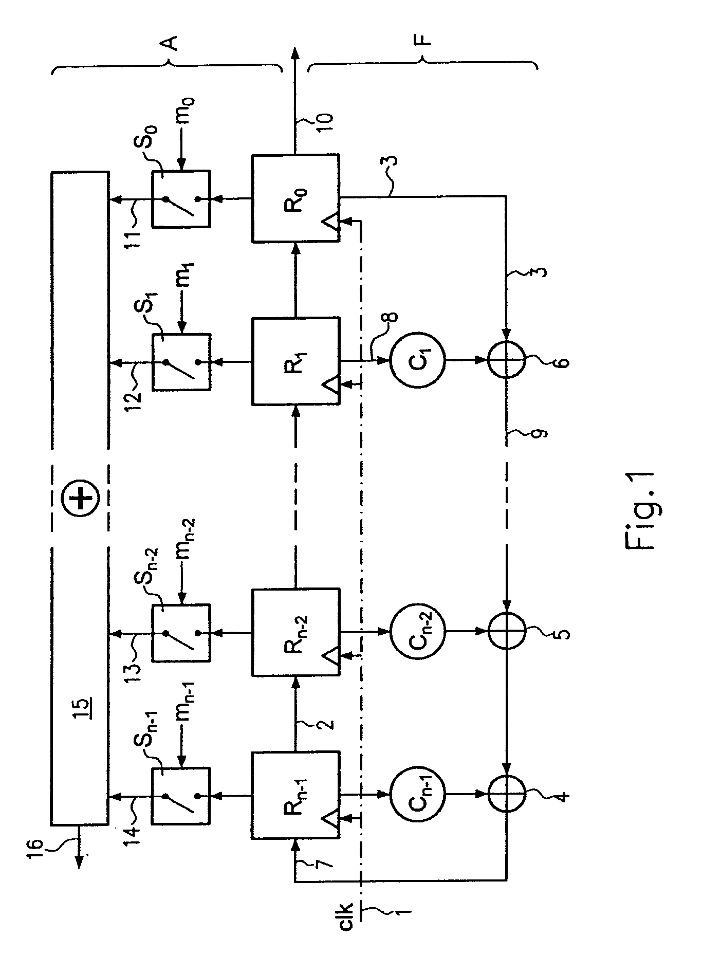
[0021]The tap mask is preferably defined by the polynomialm(x)=[xN′]mod f in the formm(x)=m0+m1·x+m2·x2+ . . . +mn−1·xn−1 with the coefficient set m0, m1, . . . , mn−1 ε {0; 1} and the computation rule that the i-th cell of the shift register arrangement is tapped off at the precise instant when mi=1, and that for each shift register operation a modulo two addition is performed for the bits which have been tapped off. In this case, one preferred method variant is characterized in that the step of determining the tap mask comprises the following steps: N is split into a sum comprising k whole numbers Ni, where k>1, in line with
[0022]N=∑i=1k⁢⁢Ni,and, if N′=N, the tap mask which is characteristic of N shift register operations is determined from the tap masks which are characteristic of the Ni, i=1, . . . , k, shift register operations on the basis of

Problems solved by technology

One disadvantage of this procedure is that the number of operations required is proportional to the magnitude of the desired shift N. This variability makes it more difficult to control the overall time sequence.
A further disadvantage is that the computational complexity and amount of time required become very large when the desired shift N has large values.
Since the generation of the desired pseudo noise sequence has to wait until the desired offset is reached, this means an unacceptable delay in transmission and reception.
The disadvantage is that a large memory area needs to be used.

Method used


Image

  • Method and device for calculating an iterated state for a feedback shift register arrangement
  • Method and device for calculating an iterated state for a feedback shift register arrangement
  • Method and device for calculating an iterated state for a feedback shift register arrangement

Examples


example 7

[0111 with L=1 corresponds to the binary splitting basis while ignoring the 4 least significant bits in the 4th group. Only 12 tap masks need to be stored (namely one of each bit) in order to be able to deal with all shifts 0≦N≦65,535 (hybrid). However, 11 polynomial multiplications are necessary in order to calculate the tap mask for N′-fold iteration of the shift register arrangement while taking into account 0≦N-N′≦15 direct shift register operations.

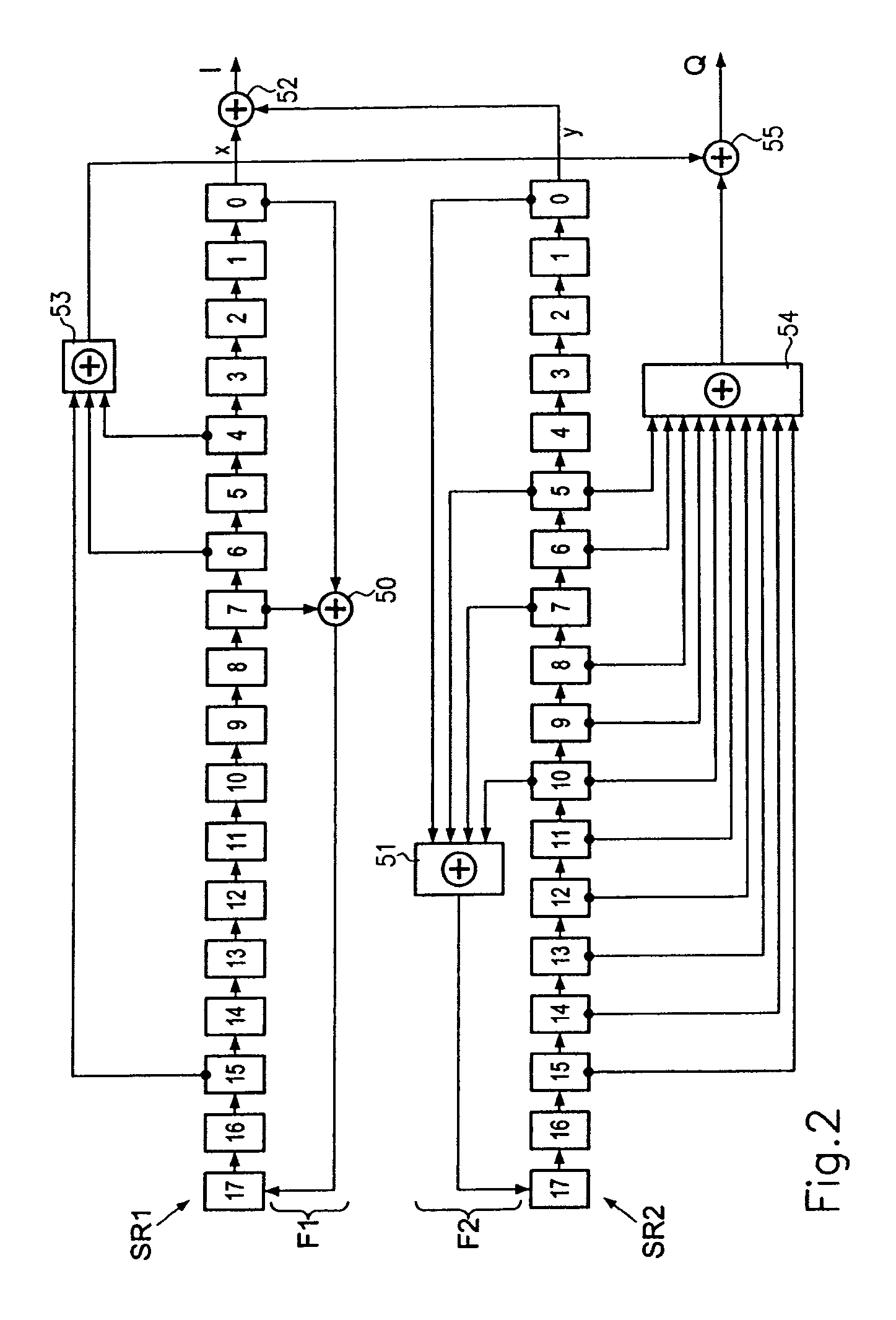
[0112]The complexity for a mask multiplication is dependent on the implementation, which can be in hardware (i.e. in the form of a hardwired circuit) or in software. Software can be used to produce a mask multiplication for tap masks of length n using approximately 5·n elementary bit operations. In the example above (n=18), approximately 90 elementary bit operations would therefore need to be started for one mask multiplication.

[0113]Table 3 compares examples 4 and 5 with the methods known in the prior art (execution of shift registe...


PUM


Abstract

A final state in a shift register arrangement is obtained from an initial state by means of N-fold iteration using an iteration rule prescribed by a characteristic polynomial f(x) of n-th order. To determine the final state, a tap mask which is characteristic of N′ shift register operations is calculated. Using the tap mask, n shift register operations are performed. This produces the n bits of an N′-fold iterated state of the shift register arrangement. Any remaining N-N′ iterations which are needed are performed in another manner.

Description

CROSS REFERENCE TO RELATED APPLICATION[0001]This application is a continuation of copending International Application No. PCT / DE03 / 00963 filed Mar. 24, 2003 which designates the United States, and claims priority to German application no. 102 16 240.9 filed Apr. 12, 2002.TECHNICAL FIELD OF THE INVENTION[0002]The present invention relates to a method and a device for determining a final state, comprising n bits and iterated N times, for a shift register arrangement from a given initial state, comprising n bits, for the shift register arrangement. The invention also relates to the generation of pseudo noise sequences shifted through N bits, which are used particularly as spreading sequences in CDMA-based mobile radio systems (CDMA: Code Division Multiple Access).BACKGROUND OF THE INVENTION[0003]In a CDMA mobile radio system, spreading sequences are used in order to be able to distinguish between different cells and subscribers in the mobile radio network. For this purpose, each user a...

Claims


Application Information

Patent Timeline
Patent Type & Authority Patents(United States)
IPC IPC(8): G06F1/02H04B1/707
CPCH04B1/70756
Inventor DENK, ROBERT
Owner INFINEON TECH AG
Learn More