Pipe structure of a windshield washer fluid feeding device

a technology of fluid feeding device and windshield washer, which is applied in the direction of liquid handling, vehicle cleaning, packaged goods type, etc., can solve the problems of short distance between the two pipes, the difficulty of integral molding the curved refill pipe, and the inability to meet the needs of the vehicle engine compartment, so as to achieve the effect of preventing the breakage of the refill pipe in winter and sufficient working spa

Inactive Publication Date: 2008-09-23
HYUNDAI MOBIS CO LTD
View PDF10 Cites 1 Cited by
  • Summary
  • Abstract
  • Description
  • Claims
  • Application Information

AI Technical Summary

Benefits of technology

[0021]Therefore, the present invention has been made in view of the above problems, and it is an object of the present invention to provide a pipe structure of a windshield washer fluid feeding device for a vehicle comprising a refill pipe, which takes the form of a multiply turned curved pipe ensuring a sufficient space between the refill pipe and a head lamp unit of the vehicle, and an auxiliary pipe integrally formed with the refill pipe, in order to ensure that the refill pipe and the auxiliary pipe define a sufficient internal space capable of covering a volume expansion of windshield washer fluid when the windshield washer fluid freezes due to a drop in temperature, resulting in prevention of damage to the refill pipe.
[0023]With such a configuration, by virtue of the fact that the refill pipe takes the form of a multiple curved pipe, it is spaced apart from a head lamp unit, thereby ensuring sufficient working space required for exchanging or checking of the head lamp unit. Further, by virtue of an integral structure of the refill pipe and the auxiliary pipe, breakage of the refill pipe in winter is prevented.

Problems solved by technology

The conventional windshield washer fluid feeding device 10, however, has a problem in that, in a mounted state thereof inside a vehicle, as can be seen from FIG. 1, the linear refill pipe 11 is positioned close to the head lamp unit 18 of the vehicle, resulting in a short distance therebetween.
In order to solve the above problem, although a solution of spacing the windshield washer fluid feeding device 10 from the head lamp unit 18 by a large distance may be considered, it complicates the design of a vehicle engine compartment, and lowers space utility thereof.
The curved refill pipe 21, however, has a problem in that it is difficult to integrally mold the curved refill pipe 21 with the windshield washer fluid reservoir tank 22.
This is because injection molding of the curved refill pipe and the windshield washer fluid reservoir tank is impossible due to the structure of the molds.
In the case of blow molding, although achievement of such an integrally molded structure is possible through a blowing process, it inevitably results in deterioration in the durability of the windshield washer fluid reservoir tank, and a difficulty in mass production thereof.
As a result of such an independent structure, if the windshield washer fluid freezes in the case of lower temperatures, a joint region between the curved refill pipe and the windshield washer fluid reservoir tank is expanded in volume at a curved portion of the refill pipe, resulting in breakage thereon.

Method used


Image

  • Pipe structure of a windshield washer fluid feeding device
  • Pipe structure of a windshield washer fluid feeding device
  • Pipe structure of a windshield washer fluid feeding device

Examples


Embodiment Construction

[0028]Reference will now be made in greater detail to a preferred embodiment of the invention, an example of which is illustrated in the accompanying drawings.

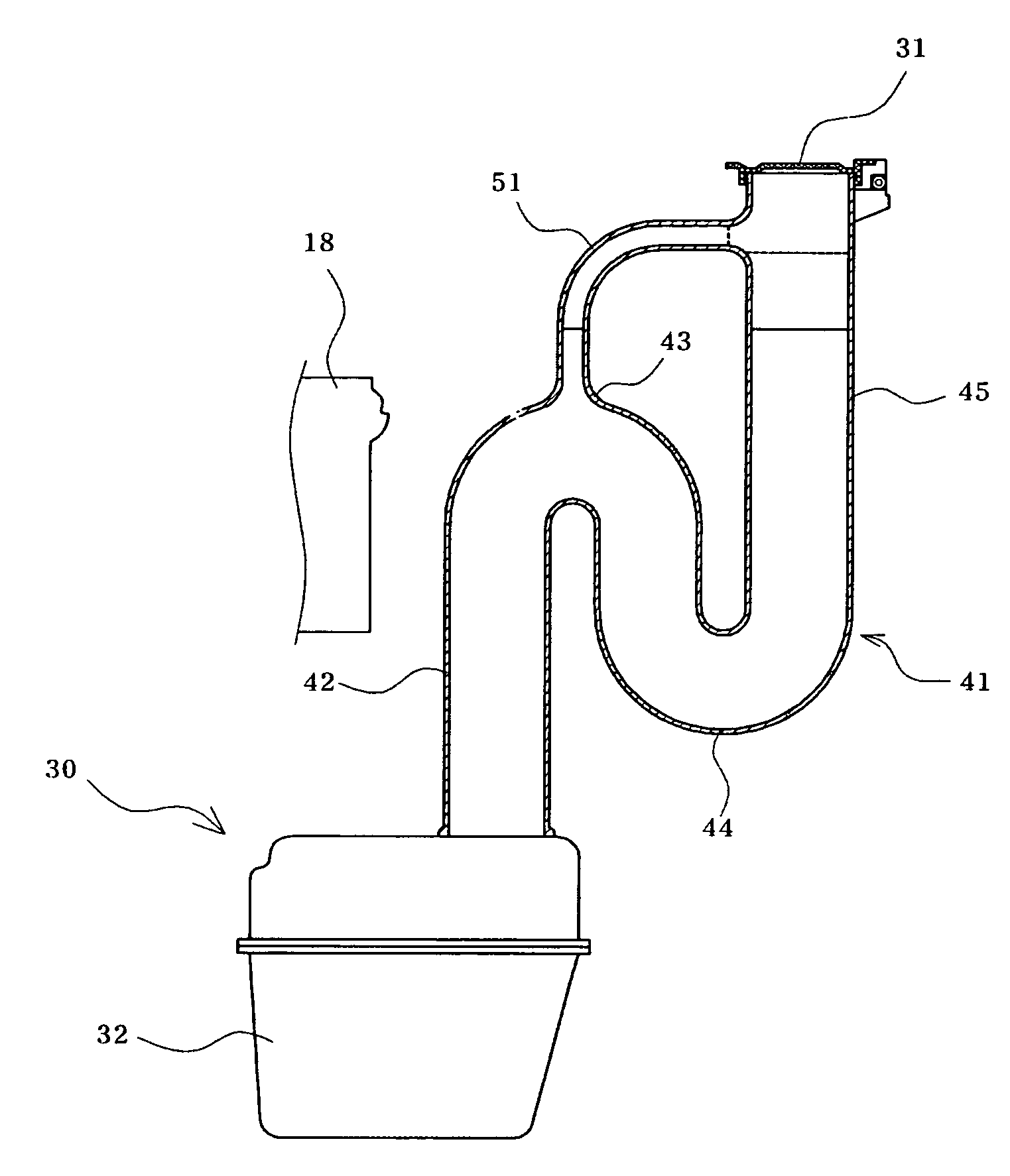
[0029]Referring to FIG. 3 illustrating, inside a vehicle, a mounted state of a windshield washer fluid feeding device having an integral pipe structure in accordance with the present invention, it comprises a refill pipe 41 taking the form of a multiple curved pipe, and an auxiliary pipe 51, which is connected at both ends thereof to certain regions of the refill pipe 41 so as to be integrally formed with the refill pipe 41. The refill pipe 41 is joined at one end thereof to a windshield washer fluid reservoir tank 32 and is closed at the other end thereof with a cap 31.

[0030]The refill pipe 41 serves as a connection passage during the replenishment of windshield washer fluid into the windshield washer fluid reservoir tank 32.

[0031]In this case, such a multiple turned curved form of the refill pipe 41 ensures a wide space betw...


PUM

PropertyMeasurementUnit
distanceaaaaaaaaaa
structureaaaaaaaaaa
durabilityaaaaaaaaaa

Abstract

A pipe structure of a windshield washer fluid feeding device for a vehicle includes a refill pipe which is used for the feeding of windshield washer fluid into a windshield washer fluid reservoir tank and has a multiply-curved form ensuring a sufficient working space between the refill pipe and a head lamp unit of the vehicle, and an auxiliary pipe connected at both ends thereof to certain portions of the refill pipe. With the combined configuration of the refill pipe and auxiliary pipe, even if the windshield washer fluid freezes, a joint region between the windshield washer fluid reservoir tank and the refill pipe is protected from damage.

Description

RELATED APPLICATION[0001]The present disclosure relates to subject matter contained in Korean application No. 2003-92951, filed on Dec. 18, 2003, which is herein expressly incorporated by reference its entirety.BACKGROUND OF THE INVENTION[0002]1. Field of the Invention[0003]The present invention relates to a pipe structure of a windshield washer fluid feeding device for a vehicle comprising a refill pipe, which is used for the feeding of windshield washer fluid into a windshield washer fluid reservoir tank and takes the form of a multiple curved pipe for ensuring a sufficient working space between the refill pipe and a head lamp unit of the vehicle, and an auxiliary pipe connected at both ends thereof to regions of the refill pipe, in order to prevent damage to the joint region between the windshield washer fluid reservoir tank and the refill pipe even in case that the windshield washer fluid contained therein freezes.[0004]2. Description of the Related Art[0005]As is well known, a ...

Claims


Application Information

Patent Timeline
Patent Type & Authority Patents(United States)
IPC IPC(8): B65B39/00B60S1/46B05B1/24B60S1/50
CPCB60S1/50Y10T137/86356B60S1/46
Inventor KIM, SOOK-KIE
Owner HYUNDAI MOBIS CO LTD
Why Eureka
Try Eureka