
Image forming apparatus

an image forming and electrostatic recording technology, applied in the field of electrostatic recording type image forming apparatus, can solve the problems of small influence on the image, drop in sharpness of an image in the main scanning direction, increase in the curvature of the field, etc., and achieve the effect of reducing the area occupied by the optical scanning devi

Inactive Publication Date: 2008-09-23
CANON KK
View PDF5 Cites 3 Cited by
  • Summary
  • Abstract
  • Description
  • Claims
  • Application Information

AI Technical Summary

Benefits of technology

This configuration minimizes the area occupied by the optical scanning device while maintaining image sharpness and quality, especially for inconspicuous colors, by optimizing the optical path lengths and focusing lenses to manage curvature and color deviation effectively.

Problems solved by technology

However, the above-described technology has the following problems.
However, as a disadvantage due to reduction of the optical path length, there occurs a problem that the curvature of field is increased.
Thus, if the optical path length of laser beam to be irradiated to the image bearing members for forming toner images using yellow, magenta, cyan and black toners is decreased, the sharpness of an image in the main scanning direction drops, which is a problem to be solved.
Even in such a case, when the freshness of the image in the main scanning direction drops, an influence upon the image is small because it is an inconspicuous color.

Method used


Image

  • Image forming apparatus
  • Image forming apparatus
  • Image forming apparatus

Examples


Embodiment Construction

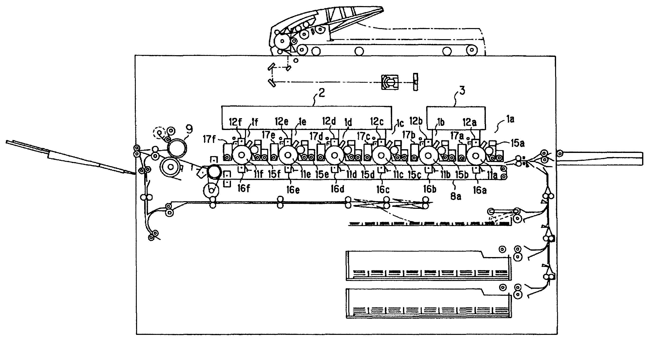
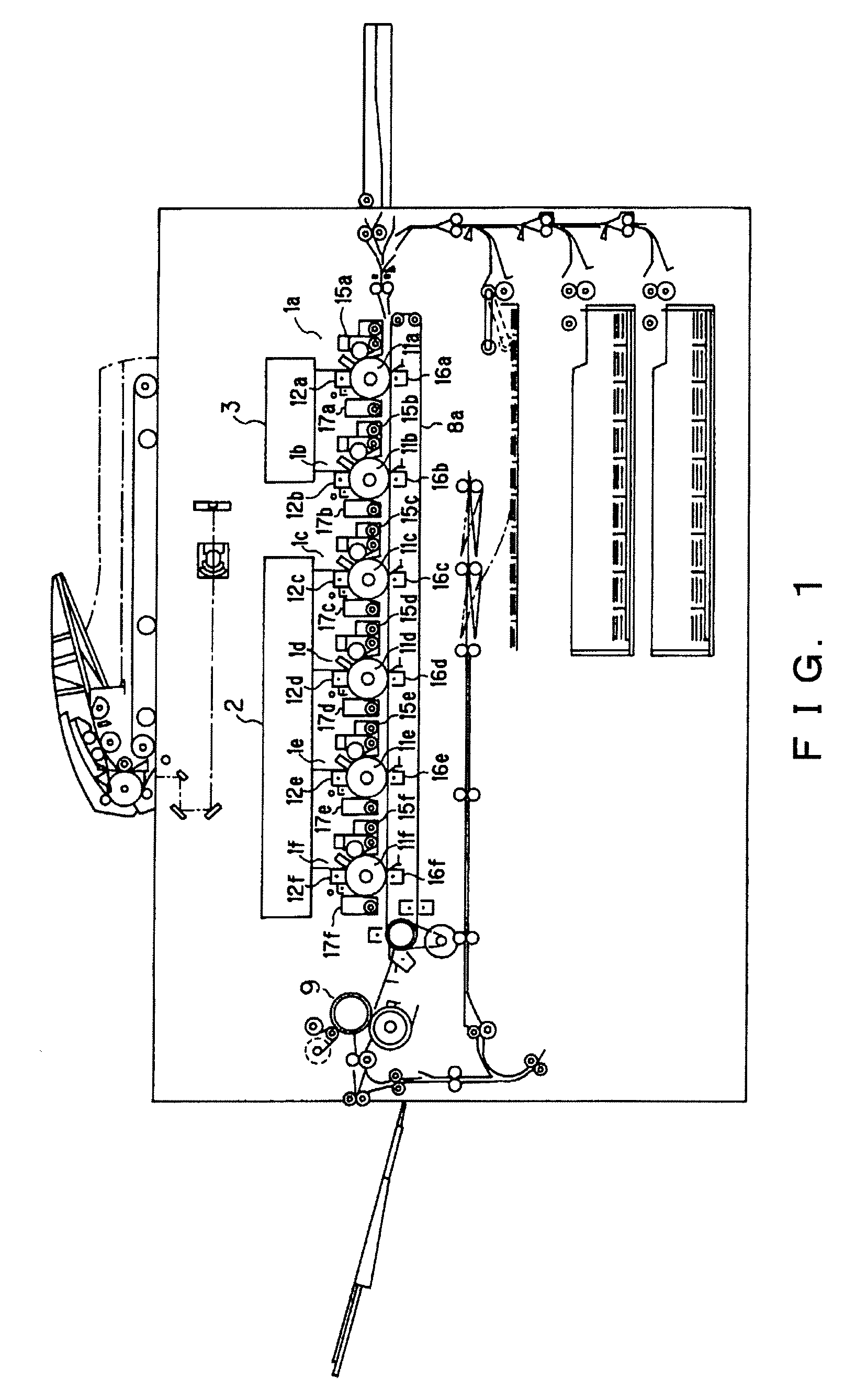
[0026]Hereinafter, one embodiment of the present invention will be described with reference to the accompanying drawings. Like reference numerals are attached to the same or corresponding components in all the drawings of the following embodiments. FIG. 1 shows an image forming apparatus according to an embodiment of the present invention. In this embodiment, a case of applying the present invention to a color image forming apparatus in which six color toners are transferred to a single transfer material (recording material) such that they are superimposed will be described.

[0027]In the image forming apparatus of the embodiment, as shown in FIG. 1, image forming units 1a, 1b, 1c, 1d, 1e, and 1f are arranged successively on the top of the endless belt-like transfer material conveying member 8a extending in the right and left directions. In the meantime, these image forming units 1a, 1b, 1c, 1d, 1e and 1f have the same configuration except for their toners.

[0028]Image bearing members ...


PUM


Abstract

A first optical scanning device for scanning image data of colors (yellow, magenta, cyan and black) which serve as the basic for formation of color image employs an optical system having optical characteristic stable to changes in temperature in common, the optical system being incorporated in a single optical box. Inexpensive resin material is employed for its lens in a second optical scanning device for scanning image data of pale color or a special color having a large tolerance amount to color deviation or spot diameter. Further, an inexpensive second optical scanning device saving space is formed by reducing the optical path length.

Description

BACKGROUND OF THE INVENTION[0001]1. Field of the Invention[0002]The present invention relates to an electrophotographic type or electrostatic recording type image forming apparatus having at least five image forming units for forming multi-color images, such as a copying machine and printer.[0003]2. Description of the Related Art[0004]With progress of the image forming apparatus in recent years, the demand for image quality has been increased and thus, an electrophotographic type image forming apparatus which adds additional colors to a conventional four-color image forming apparatus has been proposed. In such an apparatus, color toners such as pale cyan and pale magenta (hereinafter referred to as light cyan and light magenta) are added to conventional general four colors, yellow, magenta, cyan and black (Japanese Patent Application Laid-Open No. 05-35038). These pale color toners are added to intensify the image quality by reducing the granularity.[0005]In some cases, a color diff...

Claims


Application Information

Patent Timeline
Patent Type & Authority Patents(United States)
IPC IPC(8): B41J2/435B41J15/14B41J2/455B41J2/47B41J27/00
CPCB41J2/473G03G15/011G03G15/0409G03G15/0435G03G2215/0421
Inventor NAKATSU, HARUHIKO
Owner CANON KK
Learn More