Torque converter

a torque converter and converter technology, applied in the direction of fluid couplings, gearings, couplings, etc., can solve the problems of abnormal vibration in the drive system, engine loss to a conspicuous degree, and inability to use fluid couplings with large drag torque, so as to reduce the drag torque and widen the torque range of the transmission

Active Publication Date: 2008-09-30
ISUZU MOTORS LTD
View PDF9 Cites 1 Cited by
  • Summary
  • Abstract
  • Description
  • Claims
  • Application Information

AI Technical Summary

Benefits of technology

[0006]It is an object of the present invention to provide a novel torque converter which makes it possible to widen the torque range of the transmission within a limit of permissible input of the transmission and, besides, to decrease the drag torque by so controlling the transmission of torque transmitted to the stator from the pump through the turbine as will not to exceed the limit of permissible input of the transmission.

Problems solved by technology

Therefore, it is not desired to use a fluid coupling having a large drag torque as a start clutch.
A large drag torque causes the engine to lose stability to a conspicuous degree when it is idling.
Besides, the unstable revolution becomes a cause of producing abnormal vibration in the drive system.
Further, a large drag torque causes the fuel efficiency to be deteriorated during the idling operation.
When the torque converter having general characteristics is simply used, therefore, the torque becomes so great on the amplified output side as to exceed a permissible input limit of the transmission arousing a problem from the standpoint of strength.

Method used


Image

  • Torque converter
  • Torque converter
  • Torque converter

Examples


Embodiment Construction

[0018]The invention will be described in further detail with reference to the accompanying drawings illustrating a power transmission device equipped with a torque converter according to a preferred embodiment of the present invention.

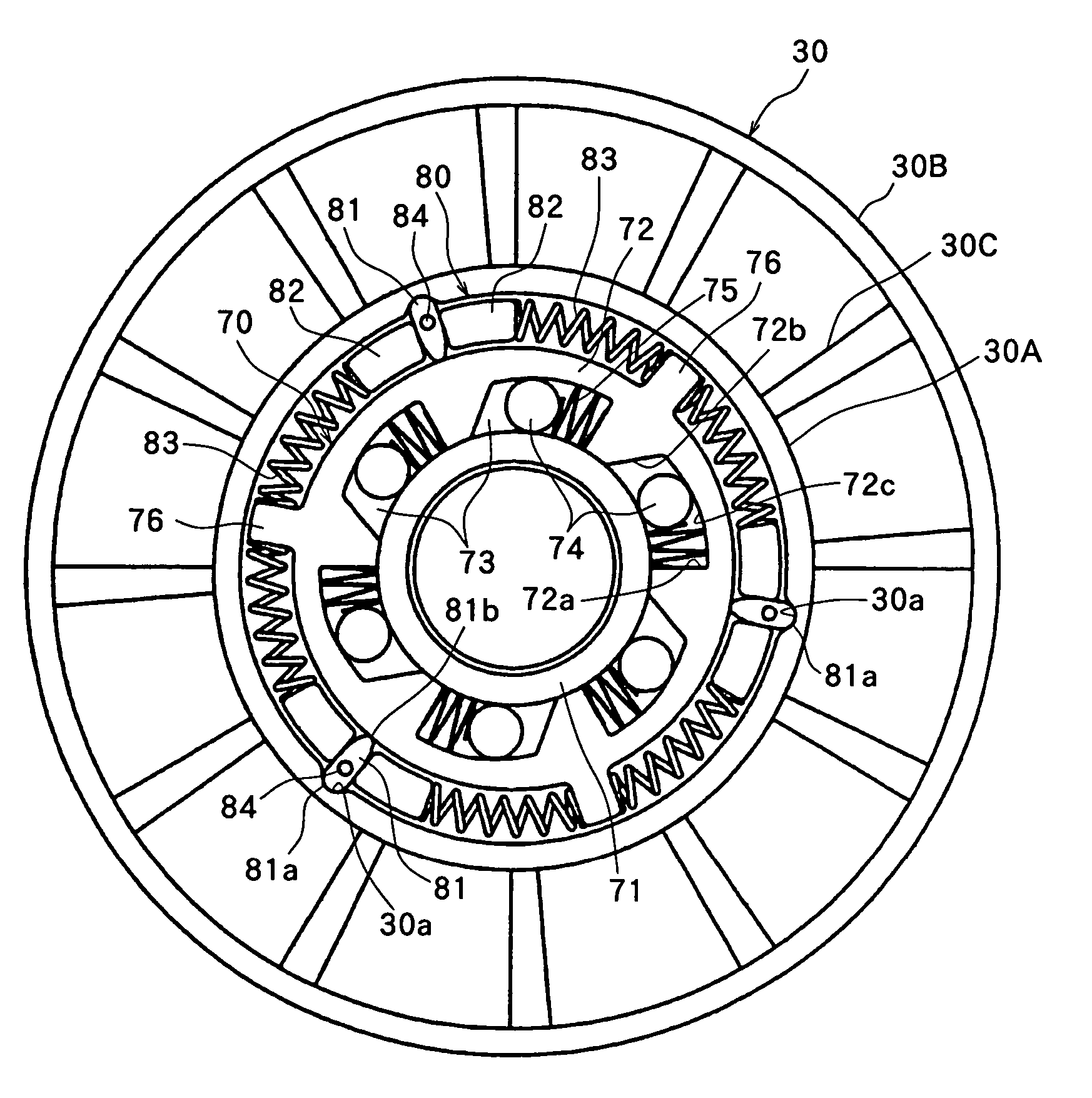
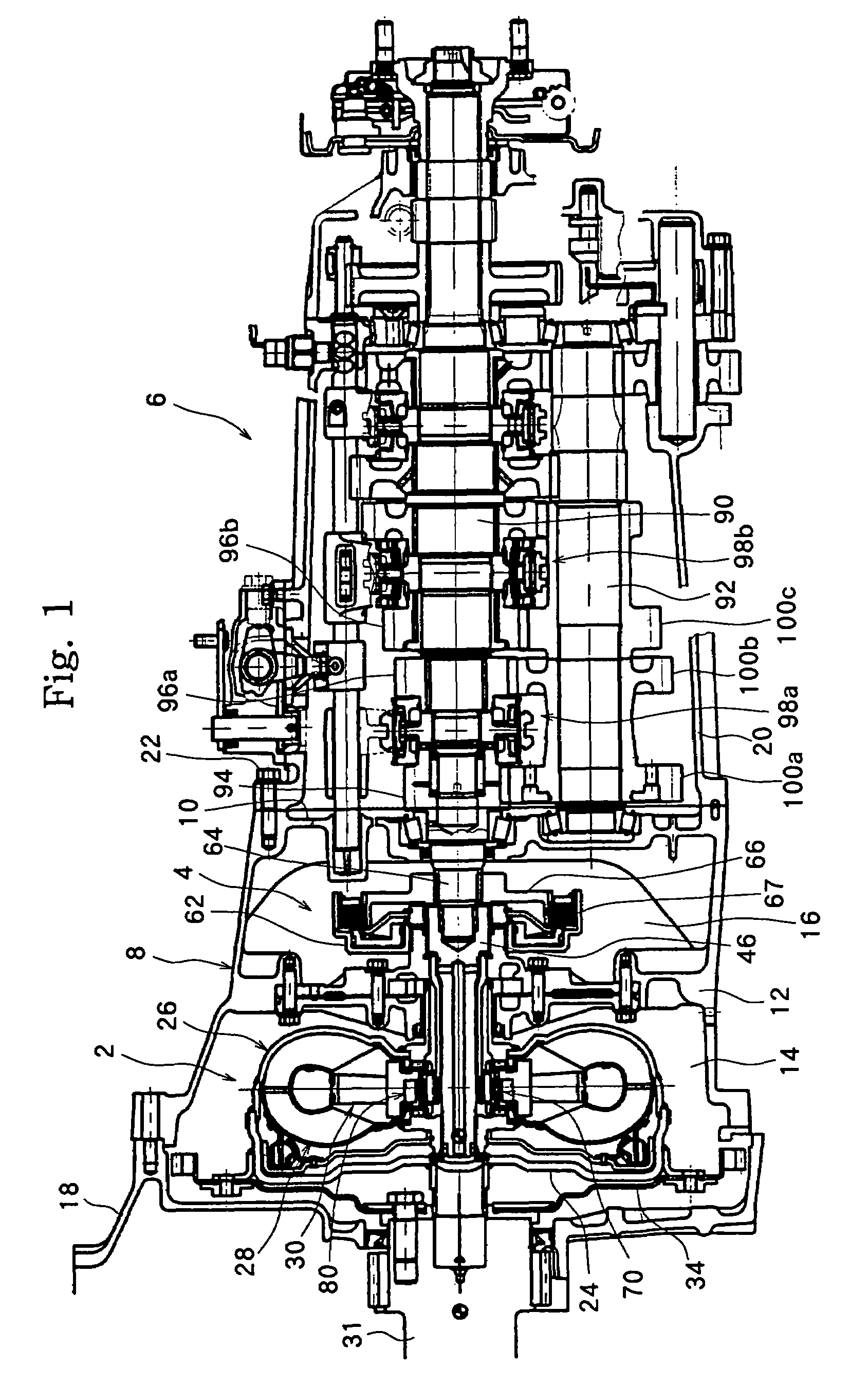
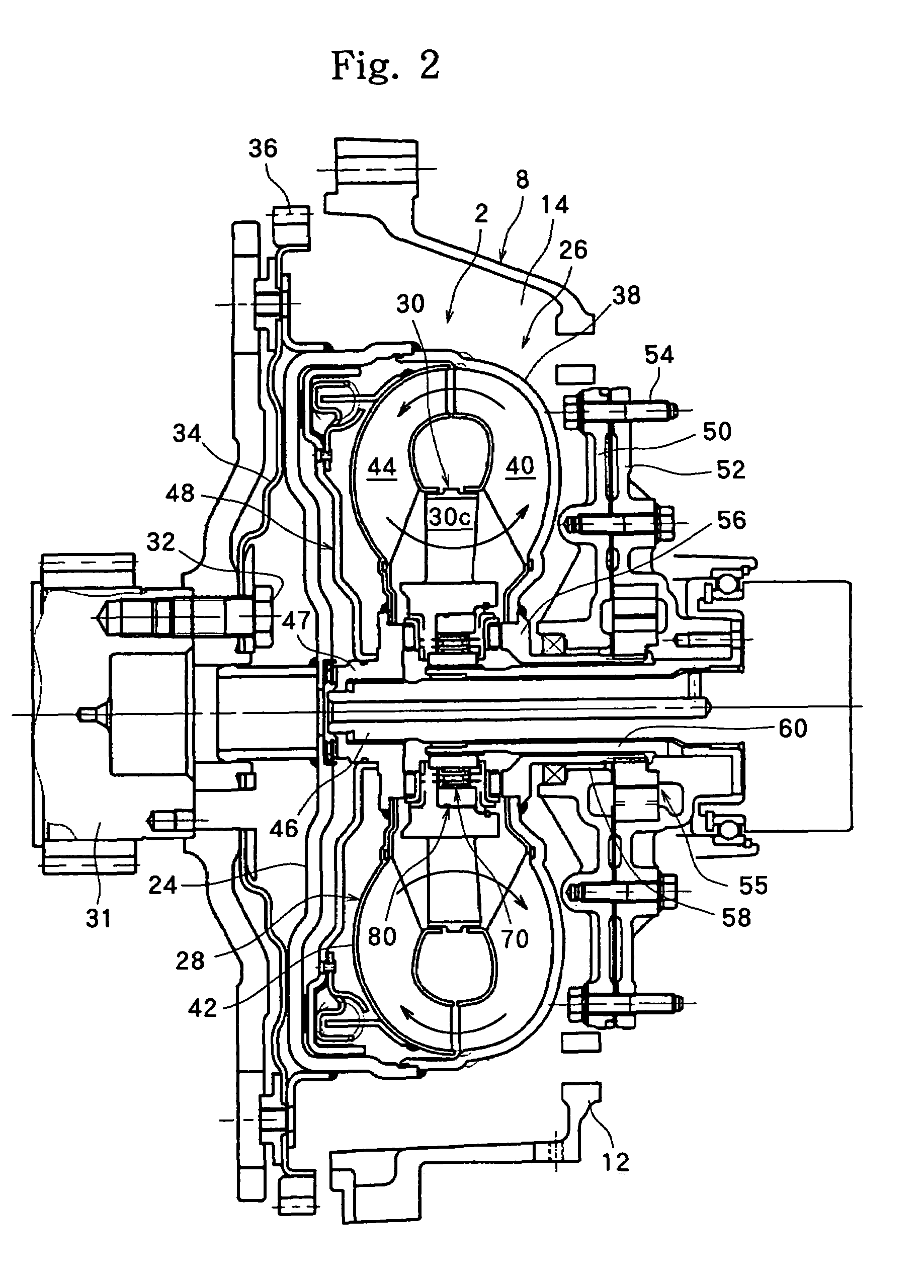
[0019]FIG. 1 is a longitudinal sectional view of an embodiment of a power transmission device equipped with a torque converter constituted according to the present invention. The power transmission device shown in FIG. 1 is constituted by a diesel engine which is a prime mover that is not shown, a torque converter 2, a wet multi-plate friction clutch 4 and a manual transmission 6, which are arranged in series.

[0020]The power transmission device that is shown is equipped with a housing 8 which contains the torque converter 2 and the wet multi-plate friction clutch 4. The housing 8 is opened on one side which is on the engine side (left side in FIG. 1) and has a partitioning wall 10 on the other side which is on the transmission side (right side in FIG. ...


PUM


Abstract

A torque converter comprises a pump having a pump shell and impellers; a turbine having a turbine shell and runners; a stator arranged between the pump and the turbine and is supported by the housing; and an operation fluid filled in the pump and in the turbine. Transmission torque limit means is arranged between the stator and the housing to so limit the transmission of torque transmitted to the stator as will not to increase in excess of a predetermined value.

Description

TECHNICAL FIELD[0001]The present invention relates to a torque converter for transmitting the rotational torque of a prime mover.BACKGROUND ART[0002]A power transmission device using a fluid coupling is representatively constituted by an engine mounted on a vehicle, a fluid coupling, a wet friction clutch and a manual transmission, which are arranged in series. The fluid coupling provided for the power transmission device for a vehicle comprises a pump having a pump shell coupled to a crank shaft of an engine such as a diesel engine, i.e., coupled to the input shaft of the fluid coupling, and a plurality of impellers radially arranged in the pump shell; and a turbine having a turbine shell arranged facing the pump and mounted on an output shaft arranged in concentric with the input shaft, and a plurality of runners radially arranged in the turbine shell. The fluid coupling contains an operation fluid for transmitting the torque (e.g., see JP-A-2002-276694).[0003]The fluid coupling i...

Claims


Application Information

Patent Timeline
Patent Type & Authority Patents(United States)
IPC IPC(8): F16D33/02F16H3/091F16H41/24F16H45/02
CPCF16H41/24F16H3/0915F16H2045/005F16H61/62F16H2041/246F16H45/02
Inventor IWAO, NOBUYUKIYAMAMOTO, YASUSHI
Owner ISUZU MOTORS LTD
Why Eureka
Try Eureka