Image pickup device including an infrared-ray cut filter

a pickup device and infrared-ray technology, applied in the field of image pickup devices, can solve the problems of relative reduction of performance and product potency, image which cannot be recognized by viewers as normal image, and is therefore unrealizable in practical us

Active Publication Date: 2008-09-30
PANASONIC CORP
View PDF6 Cites 7 Cited by
  • Summary
  • Abstract
  • Description
  • Claims
  • Application Information

AI Technical Summary

Benefits of technology

[0016]The luminous flux convergence area, where the luminous flux of the photographic light is converged down, has a small luminous-flux area. Therefore, providing the infrared-ray cut filter in the area can lead to a reduction of an advancing / retreating stroke. Because of that, a structure of the advancing / retreating mechanism unit for the infrared-ray cut filter can be simplified achieving a size reduction. Further, in the luminous flux convergence area where the luminous flux is converged down, component units (for example, iris mechanism, and the like) for applying an optical adjustment to the photographic light is conventionally provided. Therefore, the luminous flux convergence area and its periphery are originally designed to have a structure capable of incorporating the mechanism for operating the component units. The luminous flux convergence area designed to have the structure is ideal to incorporate the infrared-ray cut filter and its mechanism unit. Therefore, the components can be precisely incorporated in the area applying a minimum modification to the design. On the contrary, it is not preferable to dispose any mechanical structured component in the image-formation area of the photographic light in terms of design, in order to maintain an image-formation state with a high precision.
[0017]Further, when the infrared-ray filter is disposed in the luminous flux convergence area, an image of scar / foreign particle in the optical path of the photographic light can be substantially prevented from being image-formed in the imaging elements because the image of the scar, foreign particle, or the like, disposed in the luminous flux convergence area is not brought to a focus on the imaging elements.
[0019]It is preferable to use a thin filter (thickness of 0.1-2.0 mm) for the infrared-ray cut filter within a range where an optical property thereof can be maintained. Then, a load of the mechanism unit and a required mounting space can be further reduced, and the mechanism unit itself can be made thinner to thereby reduce the entire optical path length.

Problems solved by technology

In an ordinary image taking in a visible-ray area by means of the image element comprising the CCD, an infrared-ray area constitutes an optical band interfering the image taking because the image taking including the infrared-ray area results in an image which cannot be recognized by viewers as a normal image.
However, the extension of the entire optical length L2 is followed by a relative reduction of a performance and product potency, which is, therefore, unrealizable in practical use.

Method used


Image

  • Image pickup device including an infrared-ray cut filter
  • Image pickup device including an infrared-ray cut filter
  • Image pickup device including an infrared-ray cut filter

Examples


Embodiment Construction

[0029]Hereinafter, a preferred embodiment of the present invention is described referring to the drawings.

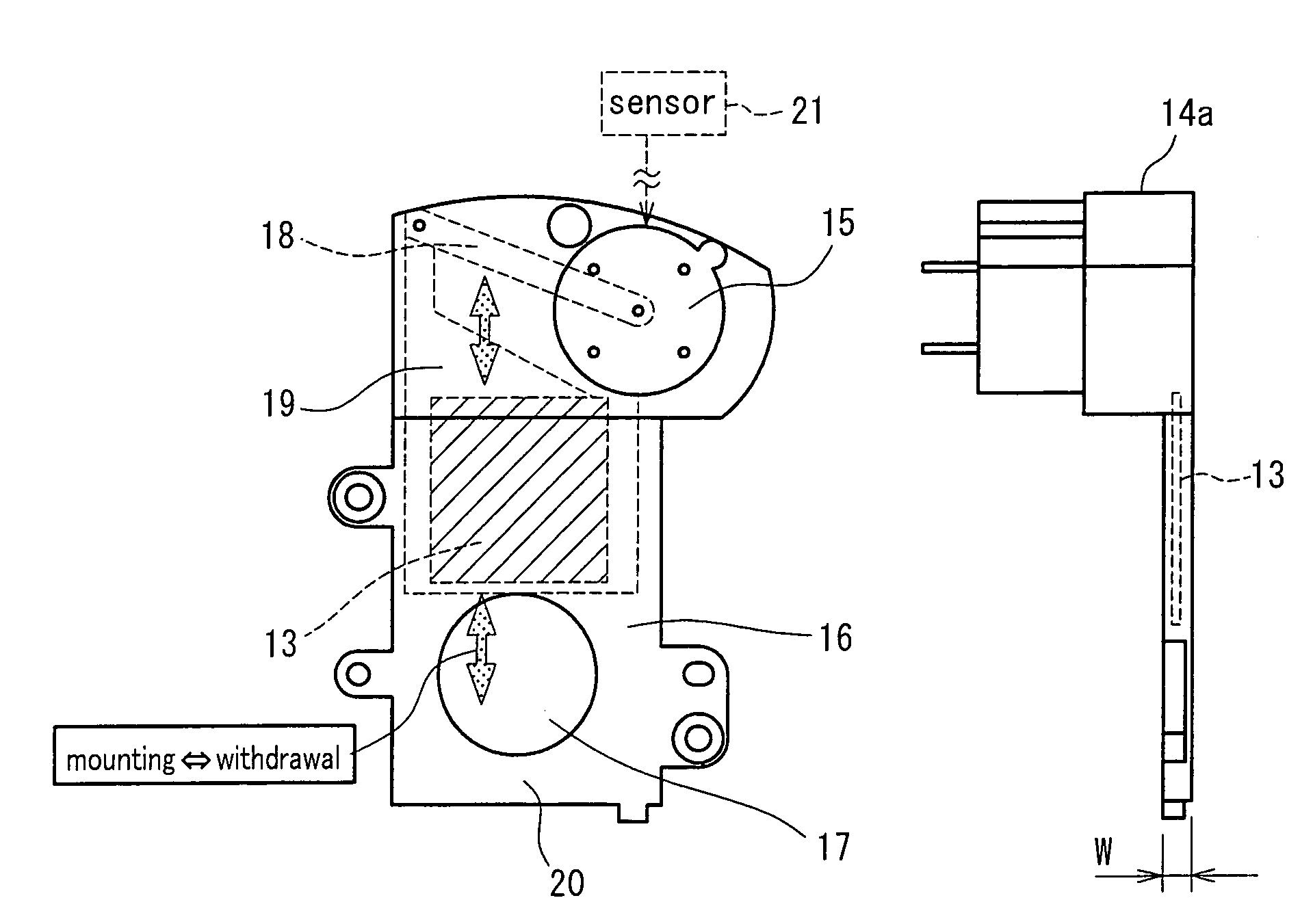
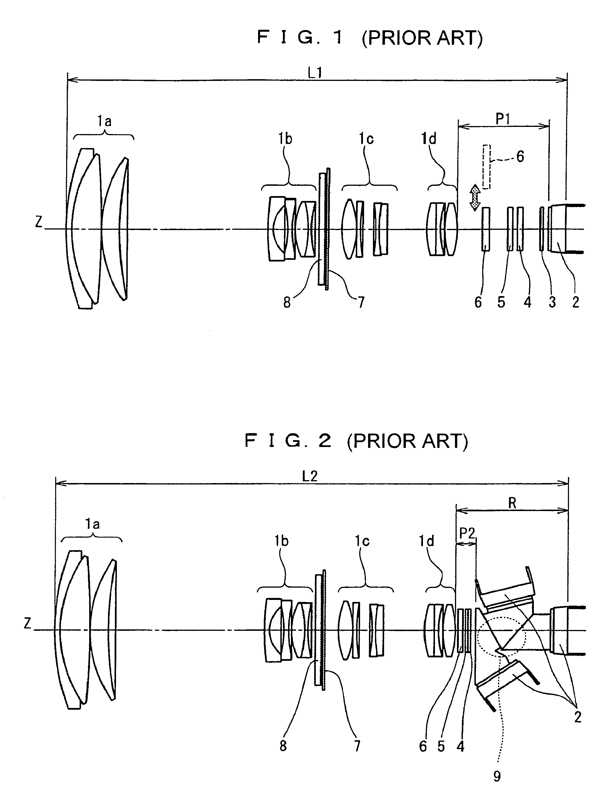
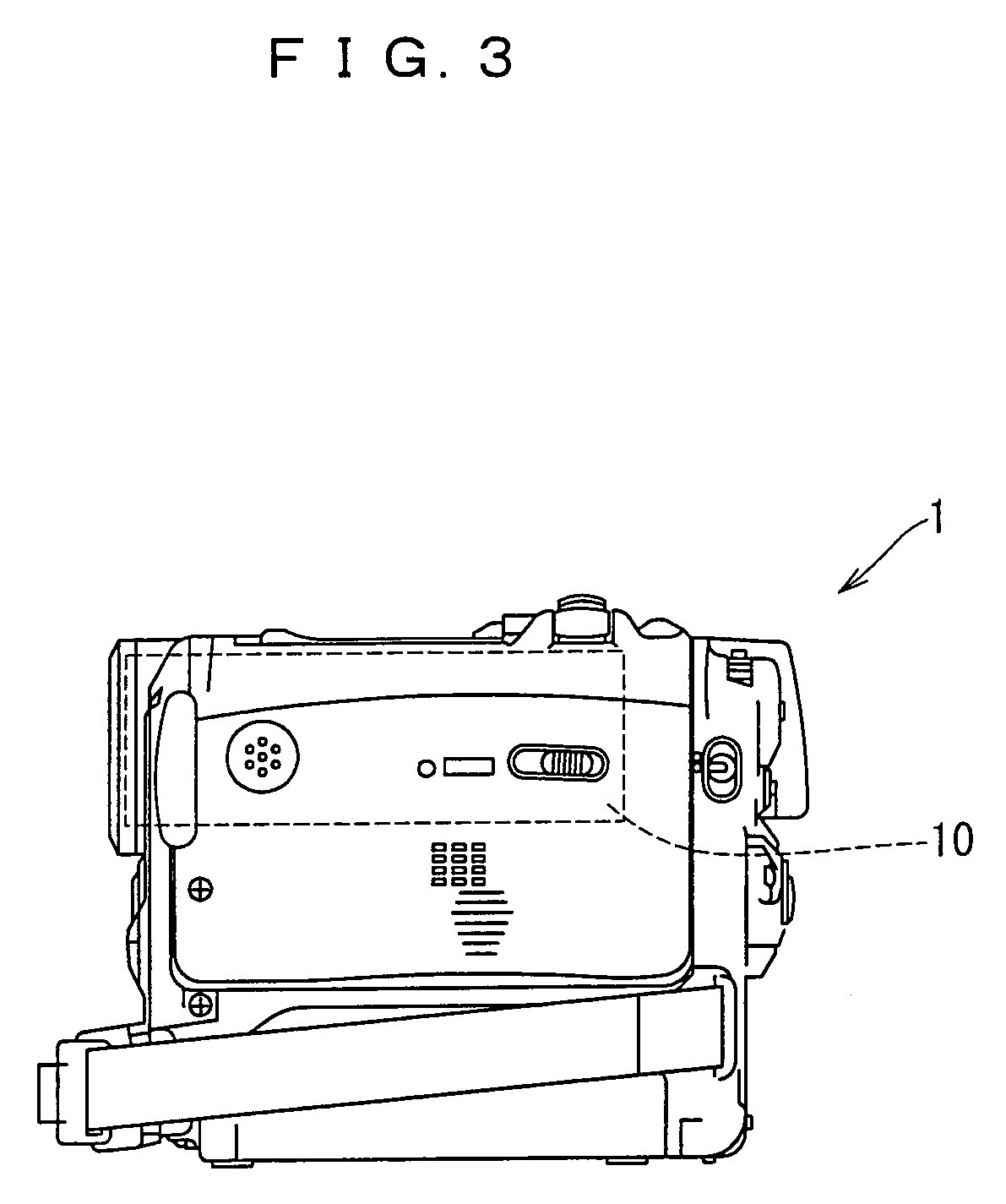
[0030]FIGS. 3-7 denote a photographing device 1 according to an embodiment of the present invention. Referring to reference symbols in the drawings, 10 denotes an optical system unit of a spectral prism type, 11 denotes a changeover switch for changeover between a conventional photographing and a low-illumination photographing, 12 denotes an infrared-ray emission auxiliary lighting unit (infrared-ray emission unit) in the case of the low-illumination photographing, 1a denotes a group of front lenses, 1b denotes a group of zoom lenses, 1c denotes a group of correction lenses for hands movement, 1d denotes a group of focusing lenses, 2 denotes imaging elements, 5 denotes an optical low-pass filter, 7 denotes an optional optical filter, 8 denotes an iris main body, 9 denotes a spectral prism, 13 denotes an infrared-ray cut filter, 14a denotes a mechanism unit, 14b denotes an iris m...


PUM


Abstract

A photographic light is spectrally separated by a spectral prism 9 provided in an image-formation area R of the photographic light whose luminous flux is adjusted by a group of lenses 1a-1d for adjusting the luminous flux so as to image-form the photographic light. Respective lights spectrally separated by the spectral prism 9 are imaged by means of the imaging elements 2. An infrared-ray element of the photographic light whose luminous flux is being adjusted is eliminated by an infrared-ray cut filter 8. The infrared-ray cut filter 8 is advanced and retreated by a mechanism unit 14a between a position in an optica path of the photographic light and a position distant from the optical path. In the foregoing constitution, the infrared-ray cut filter 8 and the mechanism unit 14a are disposed in a luminous flux convergence area R of the photographic light whose luminous flux is being adjusted by the group of lenses 1a-1d.

Description

FIELD OF THE INVENTION[0001]The present invention relates to an image pickup device having an optical system comprised of a lens system unit, optical filters, imaging elements, and the like.BACKGROUND OF THE INVENTION[0002]An optical system unit included in an image pickup device, such as a VCR-incorporated video camera, is mainly comprised of a plurality of lenses, an imaging element (CCD) and a spectroscope. The spectroscope comprises a spectral color filter or a spectral prism. In the optical system, optical components, such as iris, optical low-pass filter, and infrared-ray cut filter, are conventionally provided in an optical path of a photographic light or a peripheral area thereof in order to adjust an illumination and prevent the generation of a false color.[0003]In an ordinary image taking in a visible-ray area by means of the image element comprising the CCD, an infrared-ray area constitutes an optical band interfering the image taking because the image taking including th...

Claims


Application Information

Patent Timeline
Patent Type & Authority Patents(United States)
IPC IPC(8): H04N5/225H04N9/07
CPCH04N5/2254H04N23/55
Inventor KOKUWA, TAKASHIHINO, MASAYUKIFUNAKI, TAISEI
Owner PANASONIC CORP
Why Eureka
Try Eureka