
System, method and computer program product for developing a system-of-systems architecture model

a technology of system architecture and computer program product, which is applied in the direction of programme control, electric controller, total factory control, etc., can solve the problems of increasing the size and complexity of the engineering tasks required to design such systems, increasing program costs and risks, and reducing the practical value of the system. achieve the effect of facilitating the capture of requirements

Active Publication Date: 2008-09-30
THE BOEING CO
View PDF7 Cites 39 Cited by
  • Summary
  • Abstract
  • Description
  • Claims
  • Application Information

AI Technical Summary

Benefits of technology

This approach enables a single, managed model for both hardware and software design, facilitating efficient and effective development of SoS architectures by capturing requirements and providing an intuitive visual depiction of system structure and behavior, reducing costs and risks through improved process flow and detail.

Problems solved by technology

However, with today's advances in technology, such a design approach is becoming more difficult to implement as systems are becoming more highly integrated with other systems.
With the increase in the demand of programs to develop more complex systems and systems-of-systems, the size and complexity of the engineering tasks required to design such systems also naturally increases.
And with the increase in the size and complexity of the engineering tasks required to design complex systems and systems-of-systems, program costs and risks also increase.
Thus, whereas complex systems and systems-of-systems continue to be designed using conventional engineering techniques, such techniques generally do not provide the level of detail, discipline, process flow definition and architecture description required for the efficient and effective development of the architectures for future systems and systems-of-systems.

Method used


Image

  • System, method and computer program product for developing a system-of-systems architecture model
  • System, method and computer program product for developing a system-of-systems architecture model
  • System, method and computer program product for developing a system-of-systems architecture model

Examples


Embodiment Construction

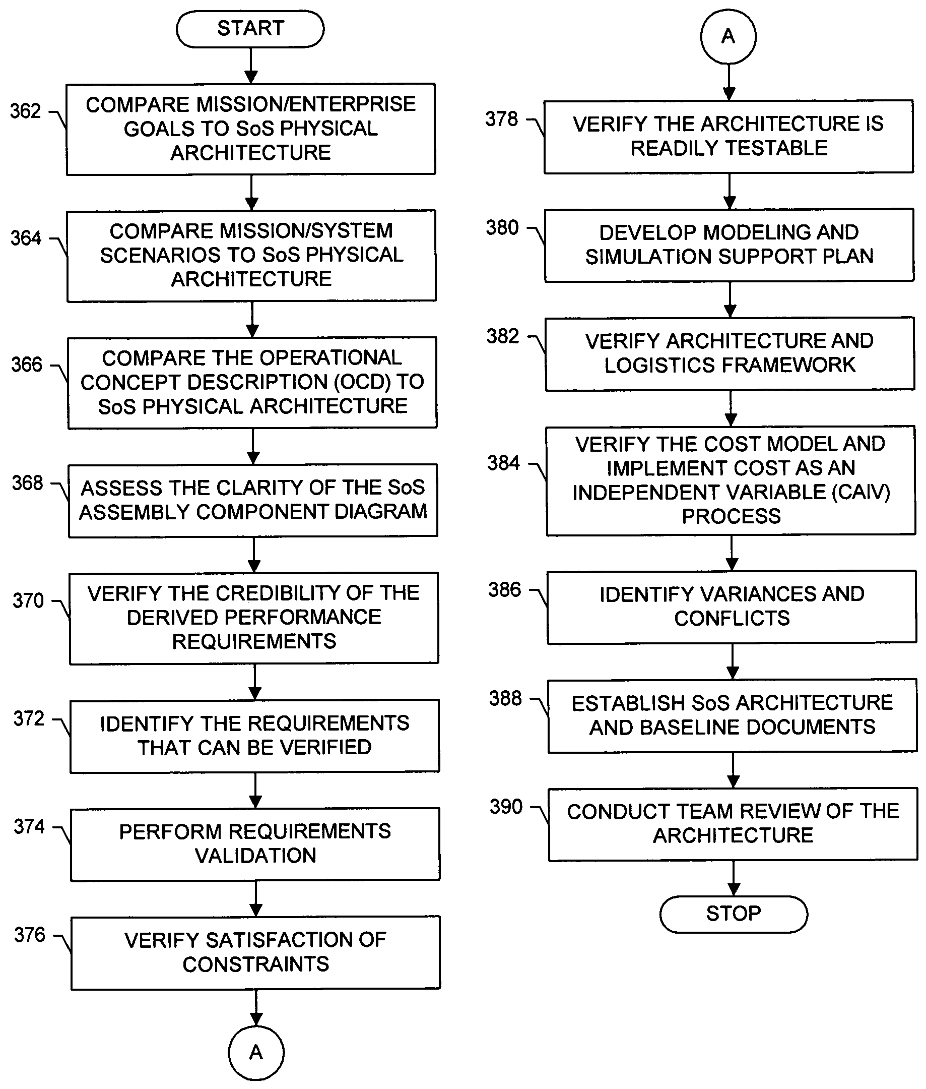
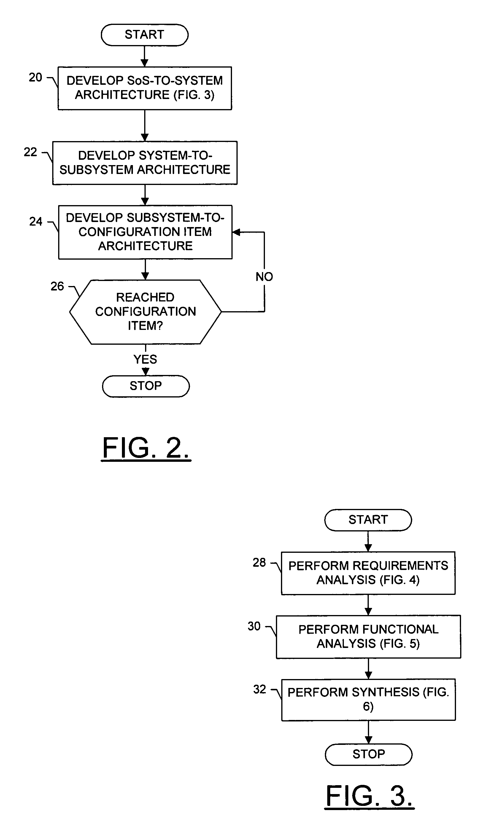
[0014]The present invention now will be described more fully hereinafter with reference to the accompanying drawings, in which preferred embodiments of the invention are shown. This invention may, however, be embodied in many different forms and should not be construed as limited to the embodiments set forth herein; rather, these embodiments are provided so that this disclosure will be thorough and complete, and will fully convey the scope of the invention to those skilled in the art.

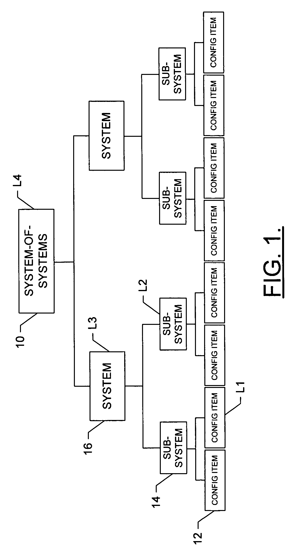
[0015]Referring to FIG. 1, a complex system-of-systems (SoS) 10 that would benefit from the system, method and computer program product of embodiments of the present invention is illustrated. The SoS consists of n levels L1 . . . Ln, with n being a positive integer. In a complex SoS, each level above the first level generally comprises a plurality of components, with the components of the level being groups of the components of the level below. For example, the system illustrated in FIG. 1 consists of f...


PUM


Abstract

A method is provided for developing an architecture model for a system-of-systems (SoS) that includes n system levels L1 . . . Ln, each of which includes at least one component of the SoS. For at least i>1, each system level Li includes at least one component of level Li-1. The method includes developing an architecture model for at least one level of the SoS. For at least i>1, the level Li-1 architecture model can be developed by developing a functional architecture model for level Li-1, and thereafter transforming the level Li-1 functional architecture model into a physical architecture model for level Li-1. The functional architecture model includes a functional and a logical structure for level Li-1. And as such, the functional architecture model is developed based upon a concurrent functional and logical decomposition of a functional architecture model developed for level Li.

Description

FIELD OF THE INVENTION[0001]The present invention relates generally to systems, methods and computer program products for developing complex logical and / or physical system architecture models and, more particularly, to systems, methods and computer program products for developing logical and / or physical system-of-systems architecture models.BACKGROUND OF THE INVENTION[0002]In many industries, most systems have been designed as single systems that operate in a given manner, oftentimes independent of other systems with which the systems may function. However, with today's advances in technology, such a design approach is becoming more difficult to implement as systems are becoming more highly integrated with other systems. In this regard, whereas a development program may have previously only designed a single system, such a program may now be more likely to design a more complex single system, or a networked system-of-systems (SoS).[0003]With the increase in the demand of programs to...

Claims


Application Information

Patent Timeline
Patent Type & Authority Patents(United States)
IPC IPC(8): G06F17/50G06F9/445
CPCG06Q10/0631G06F8/20Y02P90/02
Inventor BUTTERFIELD, MARION L.KRIKORIAN, HAIG F.SHIVANANDA, ALAKA D.GULA, JOHN A.
Owner THE BOEING CO
Learn More