Power supply/demand control system

a power supply/demand control and control system technology, applied in process and machine control, electric devices, instruments, etc., can solve the problems of low final energy efficiency, large loss of electric power transmission from electric power stations to consumers, and large loss of electric power transmission

Inactive Publication Date: 2008-09-30
PANASONIC CORP
View PDF26 Cites 34 Cited by
  • Summary
  • Abstract
  • Description
  • Claims
  • Application Information

AI Technical Summary

Problems solved by technology

In this kind of large electric power generation system, heat generating simultaneously with electric power generation cannot be used, and the loss of electric power transmission from electric power stations to consumers is large, whereby the final energy efficiency is low.
Particularly in household consumers having many distributed loads with low amount of electric power consumption, energy efficiency becomes low.
Even in this kind of distributed electric power generation, if the sale of electric power to a commercial electric power system is carried out regardless of the present electric power demand, a transmission loss occurs in the case when a node that sells electric power is distant from an electric power supplier who purchases the electric power; however, conventionally, electric power should only be generated at one location and transmitted efficiently to locations near consumers; hence, if contractors who sell electric power are few, the transmission system is not affected greatly.
However, if each node sells extran electric power, transmission cost changes greatly depending on the distributions of electric power selling locations and electric power consuming locations.
For this reason, when electric power is generated at a node, such as a dwelling house, wherein electric power demand greatly changes depending on time, season, or the like, the amount of electric power generated by the fuel cell cannot be controlled promptly depending on the change in the electric power demand at the node, whereby generated electric power becomes excessive or lacking.
This causes a problem, that is, the above-mentioned node must purchase lacking electric power from the outside in spite of having an electric power generator or sell excessive electric power to the outside.

Method used


Image

  • Power supply/demand control system
  • Power supply/demand control system
  • Power supply/demand control system

Examples


embodiment 1

[0059]Next, preferable embodiment in accordance with the present invention will be described referring to the drawings.

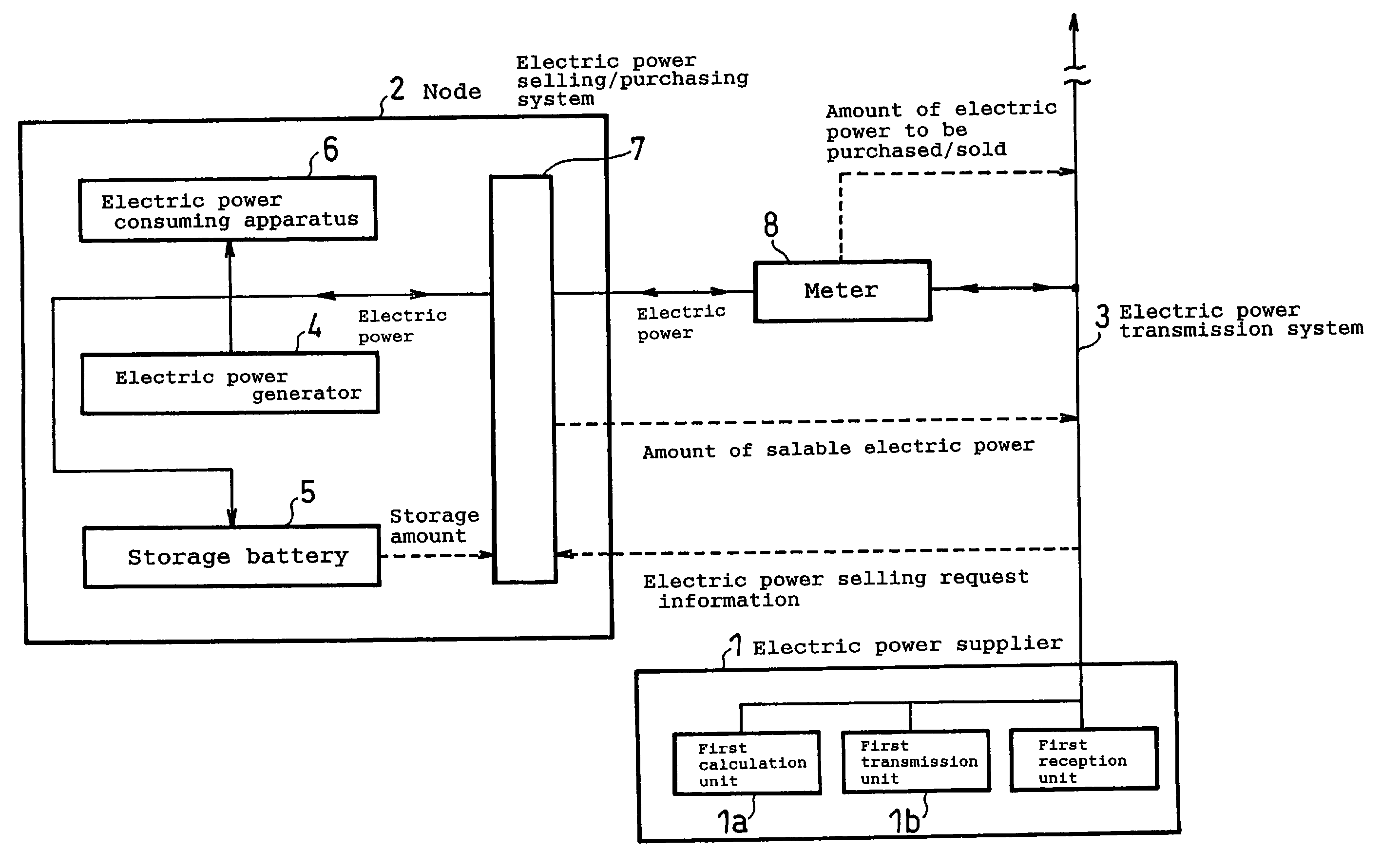
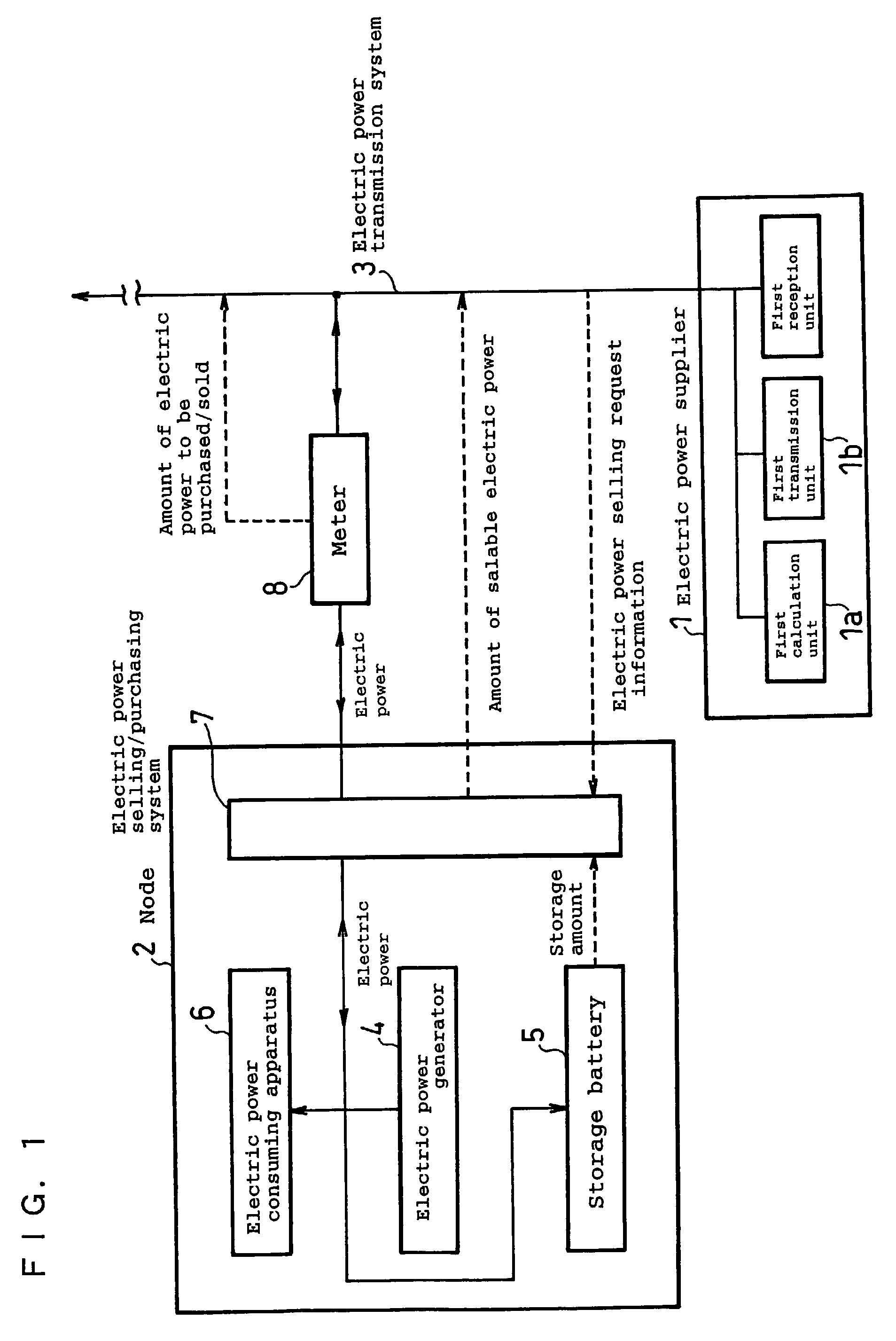
[0060]FIG. 1 is a view showing the configuration of an electric power supply and demand management system in accordance with Embodiment 1 of the present invention. The electric power supply and demand management system shown in FIG. 1 comprises an electric power supplier 1, n (n≧2) nodes 2 and an electric power transmission system 3, and the node 2 has an electric power generator 4, such as a fuel cell, a storage battery 5, and electric power consuming apparatuses 6, such as a refrigerator, a washing machine, an air conditioner and a television set, whereby temporary excessive or lacking electric power can be adjusted by the storage battery 5.

[0061]The electric power supplier 1 has a first calculation unit 1a for obtaining the difference between the total of electric power supplied from the electric power supplier 1 to the node 2 (or a group of a plurality of nodes ...

embodiment 2

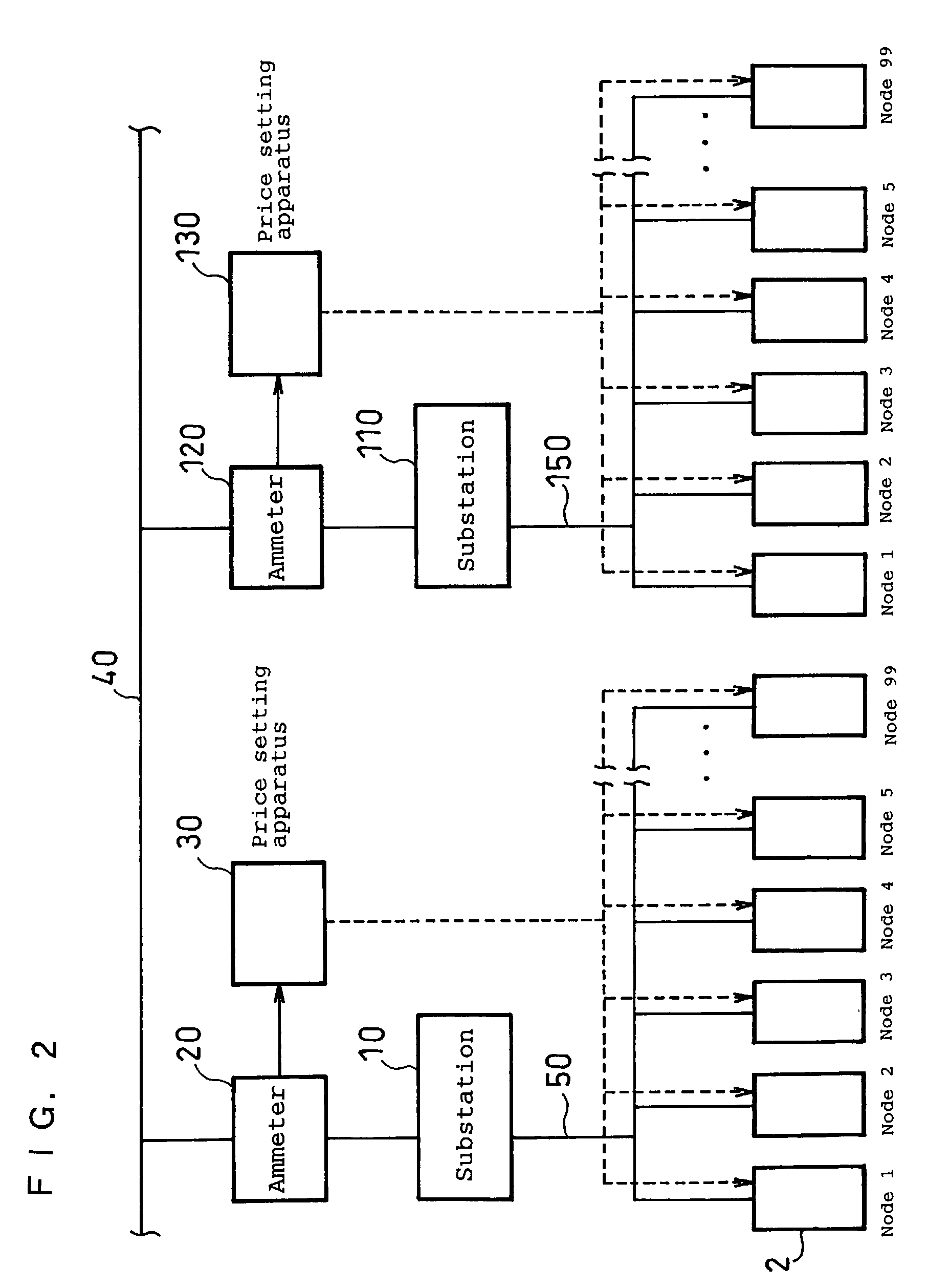
[0074]FIG. 2 is a view showing the configuration of an electric power supply and demand management system in accordance with Embodiment 2 of the present invention. In FIG. 2, electric power transmission lines 40 are high-voltage electric power transmission lines and have a high voltage in order to efficiently transmit electricity from an electric power supplier, such as a thermal electric power station, to nodes 2, such as residential areas. Electric power transmission lines 50 and electric power transmission lines 150 are transmission lines for transmitting a voltage to be supplied to each node; for example, the voltage is controlled so as to be maintained at a constant voltage in the range of about 100 to 220 V.

[0075]A substation 10 belonging to the electric power supplier is provided between the electric power transmission lines 40 and the electric power transmission lines 50 and transforms the voltage across the electric power transmission lines 40 to the voltage across the elec...

embodiment 3

[0086]FIG. 3 is a view showing the configuration of an electric power supply and demand management system in accordance with Example 3 of the present invention. Example 3 shown in FIG. 3 is the same as Example 1 in that each node has electric power consuming apparatuses, an electric power generator and a storage battery, but different in that the electric power selling / purchasing system7 used as a second calculation unit determines the selling price of electric power.

[0087]The electric power selling / purchasing system 7 sets the selling price of electric power on the basis of information, such as the current electric power supply capacity and the electric power storage amount stored in the storage battery. For example, the selling price of electric power may be set by subtracting a constant value from a limit cost per unit of electric power of the present electric power generator, or the selling price of electric power may be set lower on the basis of the electric power storage amoun...


PUM


Abstract

In order to effectively supply and demand electric power between an electric power supplier and a node or a group of nodes individually having an electric power generator, the present invention provides an electric power supply and demand management system capable of obtaining the difference between the total of electric power supplied from the electric power supplier to the node or group and the total of electric power consumed by the electric power loads of the node or group and capable of transmitting information for increasing / decreasing the amount of electric power supply so that the difference becomes smaller to the electric power supplier.

Description

TECHNICAL FIELD[0001]The present invention relates to a distributed electric power generation system comprising an electric supplier and consumers for efficiently controlling and managing the supply and demand of electric power.BACKGROUND ART[0002]In recent years, energy-saving measures have been taken significantly in view of environmental protection including the prevention of the greenhouse effect owing to carbon dioxide, although not so significantly as those during the oil crisis owing to oil shortage. Consumers of electric power are classified into industrial consumers and household consumers; the electric power consumption by the industrial consumers stays almost constant after 1970s, but the electric power consumption by the household consumers has increased twice or more after 1970s. Hence, additional energy-saving measures are required to be taken for household consumers.[0003]At present, the great majority of electric power generated by electric power supplier sides, such...

Claims


Application Information

Patent Timeline
Patent Type & Authority Patents(United States)
IPC IPC(8): G01R11/56G01F1/00G01R21/133G05D17/00G06F17/00H02J3/00H02J3/06
CPCG06Q30/00G06Q50/06H02J3/008Y04S10/54Y04S10/545Y04S50/10Y02E40/76Y02E40/70Y04S10/50H02J3/06
Inventor KANBARA, TERUHISAGYOTEN, HISAAKITANIGAWA, HIDEKAZU
Owner PANASONIC CORP
Why Eureka
Try Eureka