Cooling system with active debris separation

a technology of active debris and cooling system, which is applied in the direction of machine/engine, separation process, lighting and heating apparatus, etc., can solve the problems of lower heat transfer efficiency and higher maintenance costs, and achieve the effect of preventing plugging and overheating, reducing efficiency, and low fin coun

Inactive Publication Date: 2008-10-07
DEERE & CO
View PDF10 Cites 11 Cited by
  • Summary
  • Abstract
  • Description
  • Claims
  • Application Information

AI Technical Summary

Benefits of technology

[0004]As earlier stated, even heat exchanger cores with very low fin counts often require regular cleaning in order to prevent plugging and overheating. This leads to lower efficiency with respect to heat transfer and higher maintenance costs. Described and claimed herein is an invention that will substantially improve the atmosphere to which off-road heat exchanger cores are exposed.
[0005]The invention accomplishes the noted improvement by actively separating debris from atmospheric air prior to its flowing through the heat exchanger core. Essentially, a concentrated flow of air is blown into a first end of a chamber and exits the chamber through at least two orifices, i.e., a first exit orifice and a second exit orifice. The first exit orifice is at a second end of the chamber and, generally, parallel to the original line of flow, while the second exit orifice is generally orthogonal to the line of flow and generally contains at least one heat exchanger. As the air flows through the chamber, the mass of the debris tends to carry it along and cause it to exit the second end of the chamber. Additionally, the dimensions of the first exit orifice are small enough to cause sufficient backpressure for some of the air to flow through the heat exchanger at the second exit point. Naturally, the air flowing through the heat exchanger is pre-cleaned and substantially lower in debris content than the atmospheric air entering the first end of the chamber as the mass of the heavier debris has caused it to exit the chamber at the first exit orifice. A screen may be added to the chamber between the area of entry of the concentrated flow of air in the top of the first exit orifice to prevent light debris from floating to the heat exchanger.

Problems solved by technology

This leads to lower efficiency with respect to heat transfer and higher maintenance costs.

Method used


Image

  • Cooling system with active debris separation
  • Cooling system with active debris separation
  • Cooling system with active debris separation

Examples


Embodiment Construction

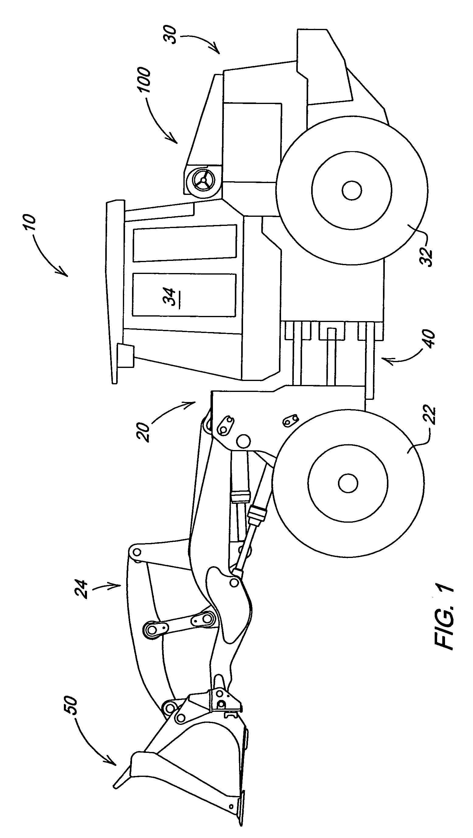
[0011]FIG. 1 illustrates a work vehicle in which the invention may be used. The particular work vehicle illustrated in FIG. 1 is an articulated four-wheel-drive motor 1 having a mainframe or body 10 that includes a front frame 20 pivotally connected to a rear frame 30 by vertical pivots 40, the loader being steered by pivoting of the front frame 20 relative to the rear frame 30 by means well known in the art. The front and rear frames 20 and 30 are respectively supported on front drive wheels 22 and rear drive wheels 32. An operator's station is provided on the rear frame 30 and is generally located above the vertical pivots 40. The front and rear drive wheels 22 and 32 propel the vehicle along the ground and are powered in a manner well known in the art.

[0012]Mounted on the front frame 20 is a linkage 24. Operatively attached to the linkage 24 is a work tool or bucket 50.

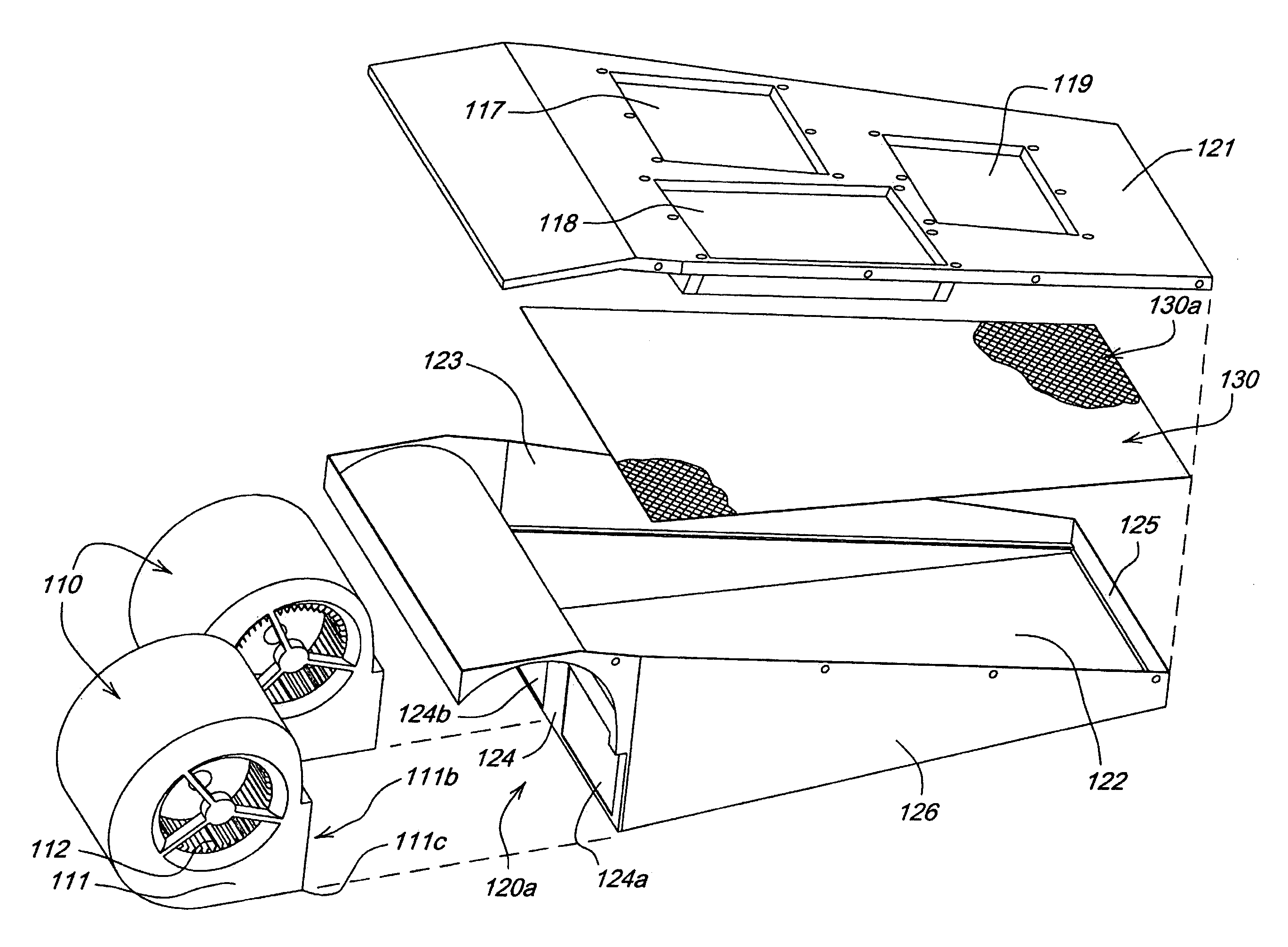
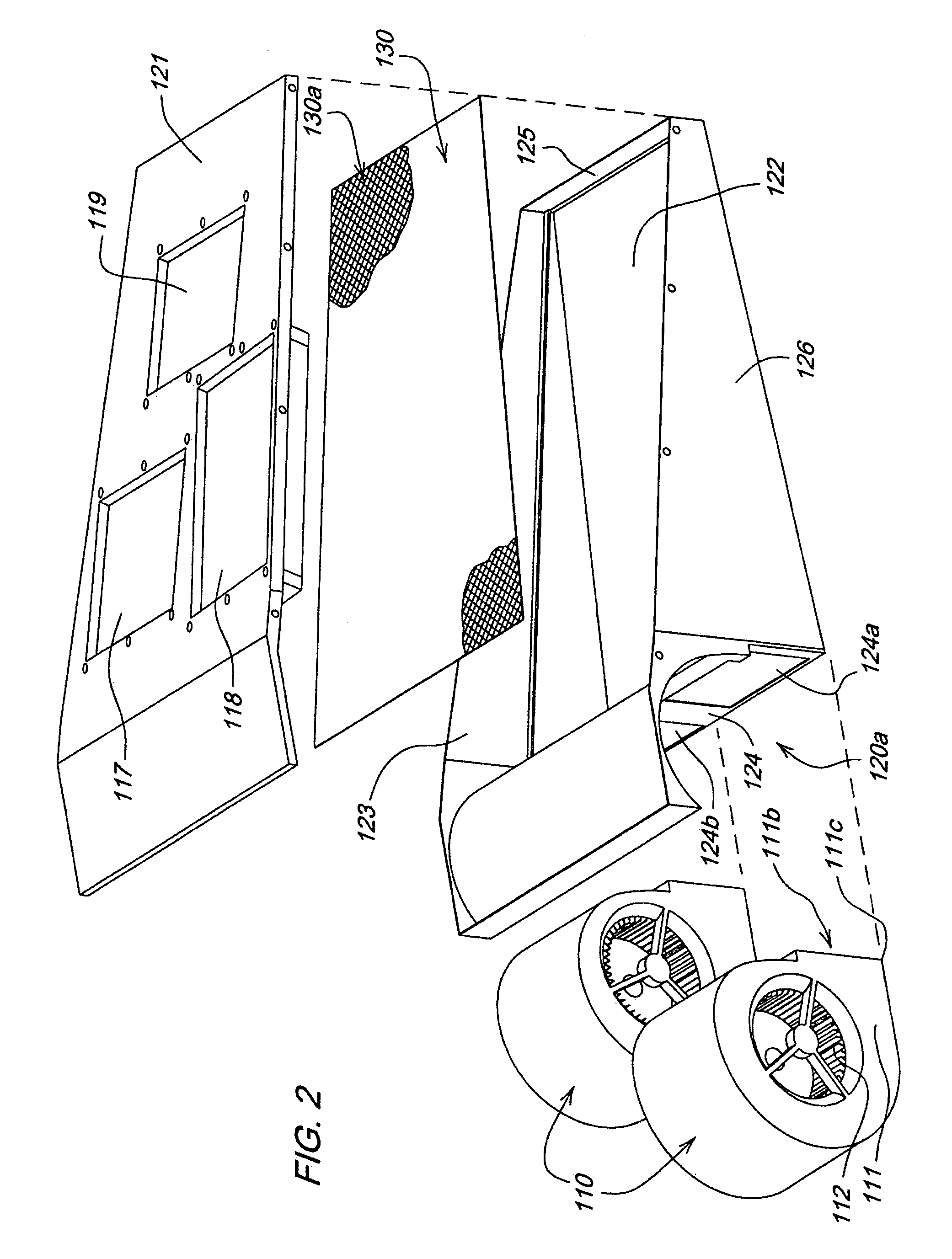
[0013]Forming a part of the rear portion 30 of the loader 1 is a cooling system 100. As illustrated in FIG. 2, t...


PUM

PropertyMeasurementUnit
lengthaaaaaaaaaa
widthaaaaaaaaaa
distanceaaaaaaaaaa

Abstract

A powered precleaner separates debris from atmospheric air through the use of a blower and a separation chamber. The chamber includes people are inlet orifice and at least two exit orifices, including an outlet orifice and an exit orifice containing at least one heat exchanger. The blower blows air and debris along an inner surface of the separation chamber and out of the outlet orifice. The outlet orifice is sized to allow large debris to exit the chamber. Sufficient backpressure is created to cause a predetermined amount of precleaned air to flow through the exit orifice containing the heat exchanger. A screen may be added to trap larger light debris and prevent it from flowing to and plugging the heat exchanger.

Description

FIELD OF THE INVENTION[0001]The invention relates to cooling systems with pre-cleaners. In particular, it relates to cooling systems operating in environments with relatively high debris content where pre-cleaning of the air is virtually required.BACKGROUND OF THE INVENTION[0002]Engine cooling theory for cars, heavy trucks and off-highway equipment is very similar. The components used to accomplish cooling goals are similar and include, for example, radiators, condensers, oil coolers, charge air coolers, etc. However, the component technologies for cars and heavy trucks differ considerably from those of off-highway equipment.[0003]Automotive cores tend to be compact with dense fin counts and the fins tend to have gill-like louvers. Such technology is appropriate for automobiles as these machines typically operate in atmospheres of relatively little debris in which cores with dense fin counts have little risk of plugging. However, such technology is usually inappropriate for off-high...

Claims


Application Information

Patent Timeline
Patent Type & Authority Patents(United States)
IPC IPC(8): F28F19/01
CPCB60K11/08F01P11/10F01P11/12F01P2003/182
Inventor RADKE, DANIEL DEANBOLLWEG, NICHOLAS EDWARDFLAMINIO, BRADLEY A.YODER, ANNE LOUISERATHSAM, TIMOTHY JAMESWOEHRLE, KIMBERLY MARIE
Owner DEERE & CO
Why Eureka
Try Eureka