
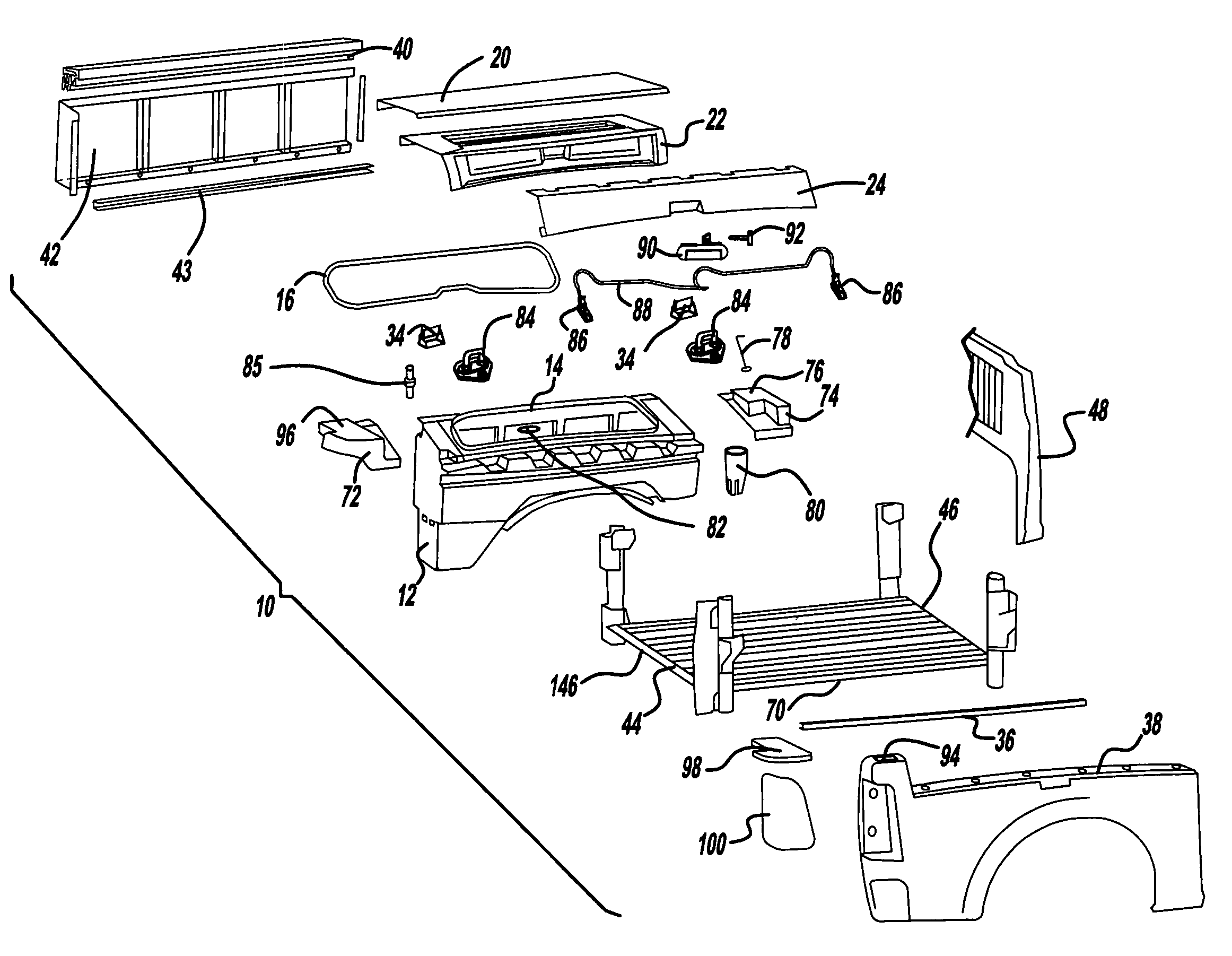
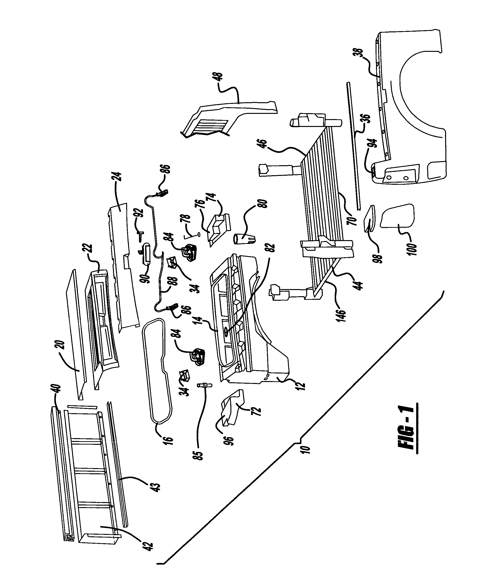
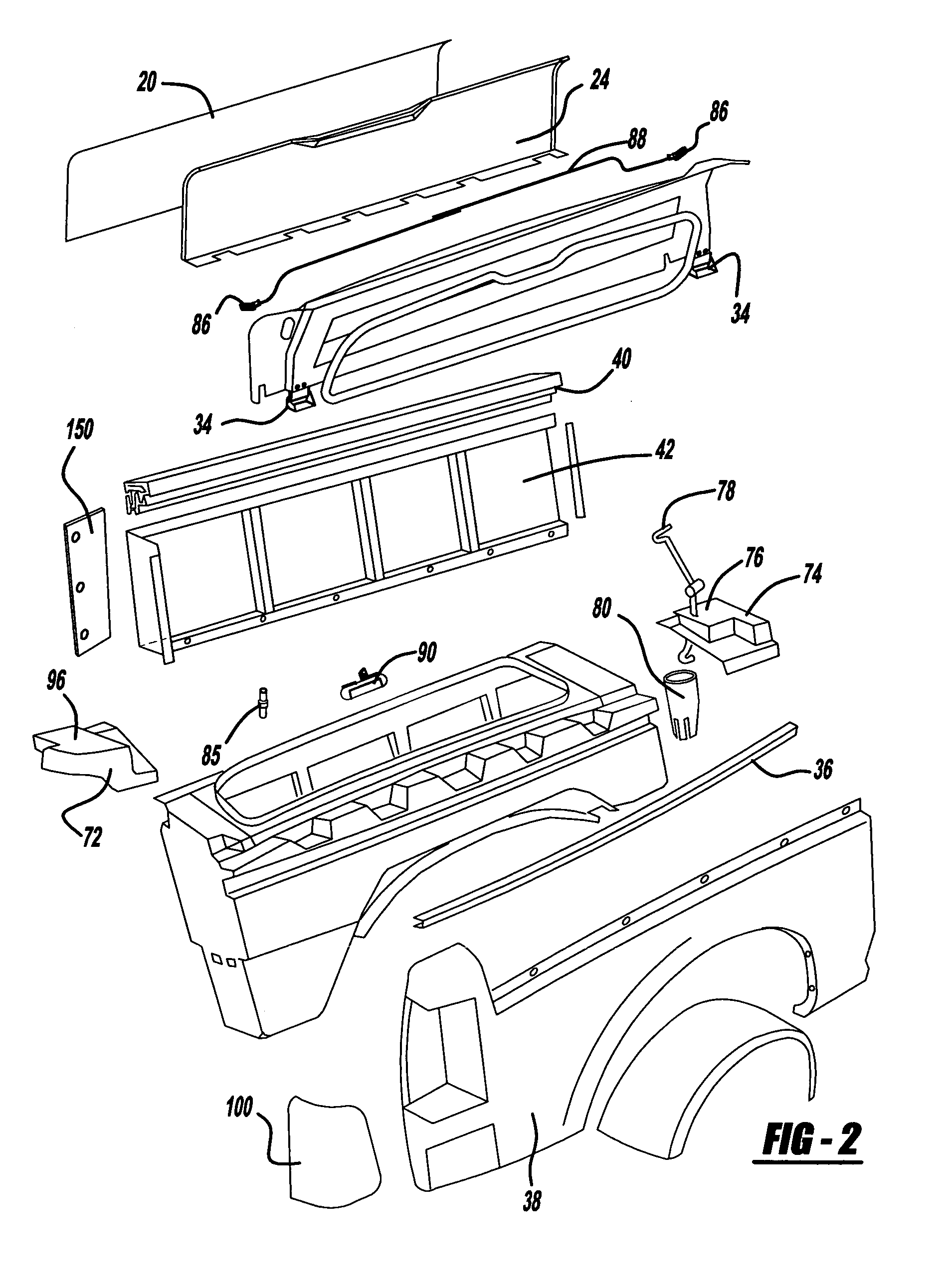
Vehicle side article transporter device

a technology for transporting devices and side articles, applied in vehicle arrangements, transportation and packaging, roofs, etc., can solve the problem of reducing the amount of space available for transporting larger items

Active Publication Date: 2008-10-07
MAGNA INTERNATIONAL INC
View PDF23 Cites 30 Cited by
  • Summary
  • Abstract
  • Description
  • Claims
  • Application Information

AI Technical Summary

Benefits of technology

The solution provides a versatile, space-efficient storage option that maintains the vehicle's original intent, allowing for secure and weather-resistant transport of items without significantly altering the vehicle's appearance, while also offering customizable dividers and additional features like lighting and power outlets.

Problems solved by technology

Pickup trucks and sport utility vehicles often have space between the inner and outer panels of the body (or bed in the case of a pickup truck) which is typically unused or underutilized.
Having an additional tool box or other type of storage device placed in the bed or the back of a sport utility vehicle reduces the amount of space available for transporting larger items.

Method used


Image

  • Vehicle side article transporter device
  • Vehicle side article transporter device
  • Vehicle side article transporter device

Examples


first embodiment

[0061]An alternate embodiment of the corner support 50 is shown in FIGS. 10-12. Instead of having a center post 52 with the brackets discussed above, the corner support 50 is made up of a first block section 128 and second block 130. The first block section 128 and the second block section 130 are both made of stamped metal, and perform all of the functions of the corner support 50. The first block section 128 has an angled section 132, and a panel 134 which serves the same function as the first side bracket 54 for supporting the upper rail 40.

[0062]The second block section 130 includes a raised bracket 136 which performs the same function as the second side bracket 56, and a lower panel 138 which performs the same function as the third side bracket 58. The second block section 130 also includes a first series of apertures 140 and a second series of apertures 142. The first series of apertures 140 are used to fasten the corner support 50 in FIG. 10 to the quarter panel 38 of a picku...

second embodiment

[0063]The first block section 128 and the second block section 130 are connected by welding. The first block section 128 and the second block section 130 both have weld points 152 which are used to weld the first block section 128 and the second block section 130 together. Having the corner support 50 formed of the first block section 128 and the second block section 130 reduces the overall number of components and improves the ability of the corner support 50 to meet any tolerance requirements. Additionally, the first block section 128 has a tab 154 which is cut out of the first block section 128 which also as weld points 152 for being welded to the second block section 130. Both of the first block section 128 and the second block section 130 have bottom tabs 156 which have weld points 152. To connect the corner support 50 of the second embodiment to the structural bed assembly 44, the structural bed assembly 44 includes a rear rail 158 which is positioned between, and welded to ea...


PUM


Abstract

The present invention is a container for a light-duty automobile such as a light-duty pickup truck or sport-utility vehicle having at least one opening, operably associated with the quarter panel of an automobile, an inner wall operably associated with the container, and a cover having a closed position and an open position operably associated with the opening. The cover includes a door inner, and a door outer. The invention also includes a first rail positioned between the container and the quarter panel. The container is integrally formed with the first rail, and is located between the first rail and the inner wall. The first rail supports the container, and the cover can be moved from the open position to the closed position, allowing access to the container.

Description

FIELD OF THE INVENTION[0001]The present invention relates to a formed storage unit for use in light duty pickup trucks and sport-utility vehicles.BACKGROUND OF THE INVENTION[0002]Pickup trucks and sport utility vehicles often have space between the inner and outer panels of the body (or bed in the case of a pickup truck) which is typically unused or underutilized. The space is most prevalent around the area of the wheel house enclosures of both pickup trucks and sport utility vehicles. It is often desired to store and transport smaller items, where the large space in the bed of a pickup or the back of a sport utility vehicle is unnecessary. Typically, to transport smaller items, a toolbox or other type of storage device is placed in the pickup bed or the back of the sport utility vehicle. Having an additional tool box or other type of storage device placed in the bed or the back of a sport utility vehicle reduces the amount of space available for transporting larger items.[0003]Acco...

Claims


Application Information

Patent Timeline
Patent Type & Authority Patents(United States)
IPC IPC(8): B60N3/12
CPCB60R5/00B62D33/0273
Inventor HENDERSON, JACK VERNONMACLEAN, PETER VINCENT
Owner MAGNA INTERNATIONAL INC
Learn More