Method and apparatus for cooling gas turbine rotor blades

a gas turbine and rotor blade technology, applied in the field of gas turbine engines, can solve the problems of inability to provide film cooling, and inability to maintain the internal pressure in the third cavity in all cases

Active Publication Date: 2008-10-07
GENERAL ELECTRIC CO
View PDF15 Cites 26 Cited by
  • Summary
  • Abstract
  • Description
  • Claims
  • Application Information

AI Technical Summary

Problems solved by technology

However, adequate internal pressure in the third cavity may not be able to be maintained in all cases.
The second cavity or the cavity adjacent and upstream of the third cavity has adequate pressure but is located too far forward to be able to provide film cooling where it is needed.

Method used


Image

  • Method and apparatus for cooling gas turbine rotor blades
  • Method and apparatus for cooling gas turbine rotor blades
  • Method and apparatus for cooling gas turbine rotor blades

Examples


Embodiment Construction

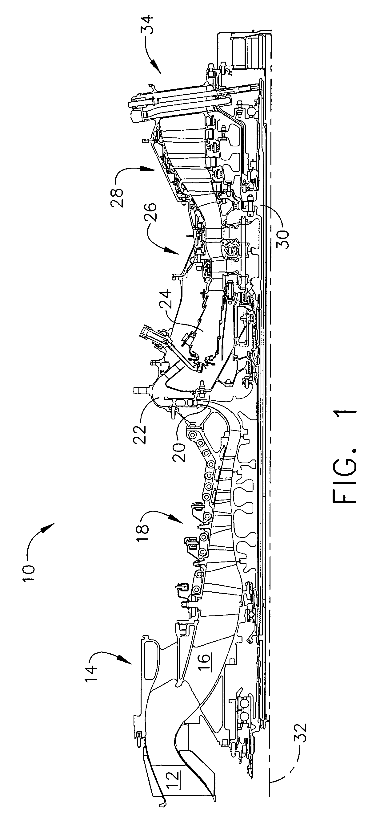
[0011]FIG. 1 is a schematic cross-sectional illustration of a gas turbine engine 10 including an inlet 12, an inlet particle separator 14, core inlet guide vanes 16. Engine 10 also includes in serial flow communication an axial compressor 18, a radial compressor 20 or impellor, and a deswirler diffuser 22. Downstream from deswirler diffuser 22 is a combustor 24, a high pressure turbine 26 and a power turbine 28.

[0012]In operation, air flows through inlet 12 to axial compressor 18 and to radial compressor 20. The highly compressed air is delivered to combustor 24. The combustion exit gases are delivered from combustor 24 to high pressure turbine 26 and power turbine 28. Flow from combustor 24 drives high pressure turbine 26 and power turbine 28 coupled to a rotatable main turbine shaft 30 aligned with a longitudinal axis 32 of gas turbine engine 10 in an axial direction and exits gas turbine engine 10 through an exhaust system 34.

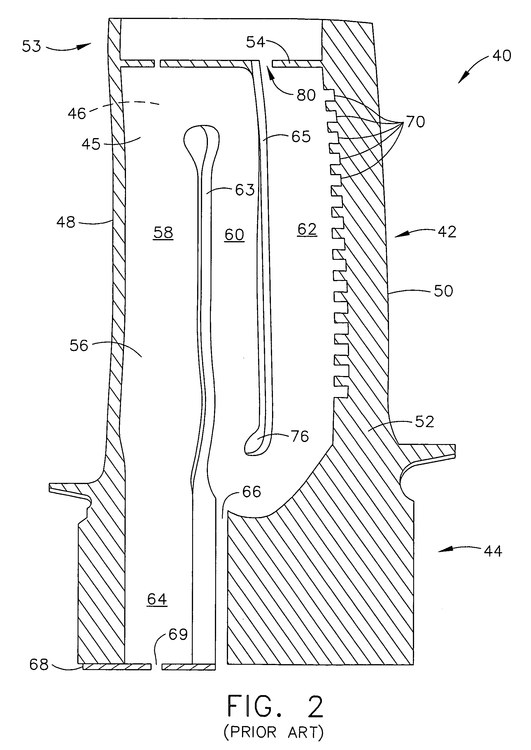
[0013]FIG. 2 is a perspective internal schematic illus...


PUM


Abstract

Methods and apparatus for cooling gas turbine rotor blades is provided. The rotor blades include an airfoil having a pressure sidewall and a second suction sidewall connected together at a leading edge and a trailing edge, such that an internal three pass serpentine cooling circuit is formed therebetween. The cooling circuit includes radially extending first, second, and third serpentine cooling cavities partially separated by, in axially aft succession, a first radially extending internal rib and a second internal rib. The second rib includes a radially inner first portion and a radially outer portion wherein the radially outer portion is angled obliquely with respect to the first portion.

Description

BACKGROUND OF THE INVENTION[0001]This invention relates generally to gas turbine engines and more particularly, to methods and apparatus for cooling gas turbine engine rotor assemblies.[0002]Turbine rotor assemblies typically include at least one row of circumferentially-spaced rotor blades. Each rotor blade includes an airfoil that includes a pressure side, and a suction side connected together at leading and trailing edges. Each airfoil extends radially outward from a rotor blade platform. Each rotor blade also includes a dovetail that extends radially inward from a shank extending between the platform and the dovetail. The dovetail is used to mount the rotor blade within the rotor assembly to a rotor disk or spool. Known blades are hollow such that an internal cooling cavity is defined at least partially by the airfoil, platform, shank, and dovetail.[0003]At least some known high pressure turbine blades include an internal cooling cavity that is serpentine such that a path of coo...

Claims


Application Information

Patent Timeline
Patent Type & Authority Patents(United States)
IPC IPC(8): F01D5/08
CPCF01D5/187F05D2250/185F05D2260/202F05D2250/314F01D5/20
Inventor HOOPER, TYLER F.REDDY, BHANUZHU, GAOQIUMANNING, ROBERT F.
Owner GENERAL ELECTRIC CO
Why Eureka
Try Eureka