Constant current generator

a generator and constant current technology, applied in the direction of thyristor, electrical equipment, emergency protective arrangements for limiting excess voltage/current, etc., can solve the problems of difficult to adjust parameters, cannot withstand reverse, and the silicon surface required to make the component is relatively larg

Inactive Publication Date: 2008-10-07
STMICROELECTRONICS SRL
View PDF24 Cites 6 Cited by
  • Summary
  • Abstract
  • Description
  • Claims
  • Application Information

AI Technical Summary

Benefits of technology

[0023]According to an embodiment of the present invention, the strip is a lightl

Problems solved by technology

Such a component has the following disadvantages:it incorporates an intrinsic diode in anti-parallel and thus cannot withstand reverse voltages;it is technologically difficult to adjust the parameters which set the limiting current, especially the threshold voltage of the MOS transistor and the resistance of the preformed channel;the silicon surface required to make the component is relatively large.
1) it is limited to the presence of low voltages, that is, the voltage between terminals A and B must not exceed a threshold value linked to the direct breakdown voltage of transistor T; this circuit operates all the better as the transistor has a high gain; this limits its breakdown voltage and increases breakdown risks;
2) in the case where the component is inserted in a circuit where the biasing bet

Method used


Image

  • Constant current generator
  • Constant current generator
  • Constant current generator

Examples


Embodiment Construction

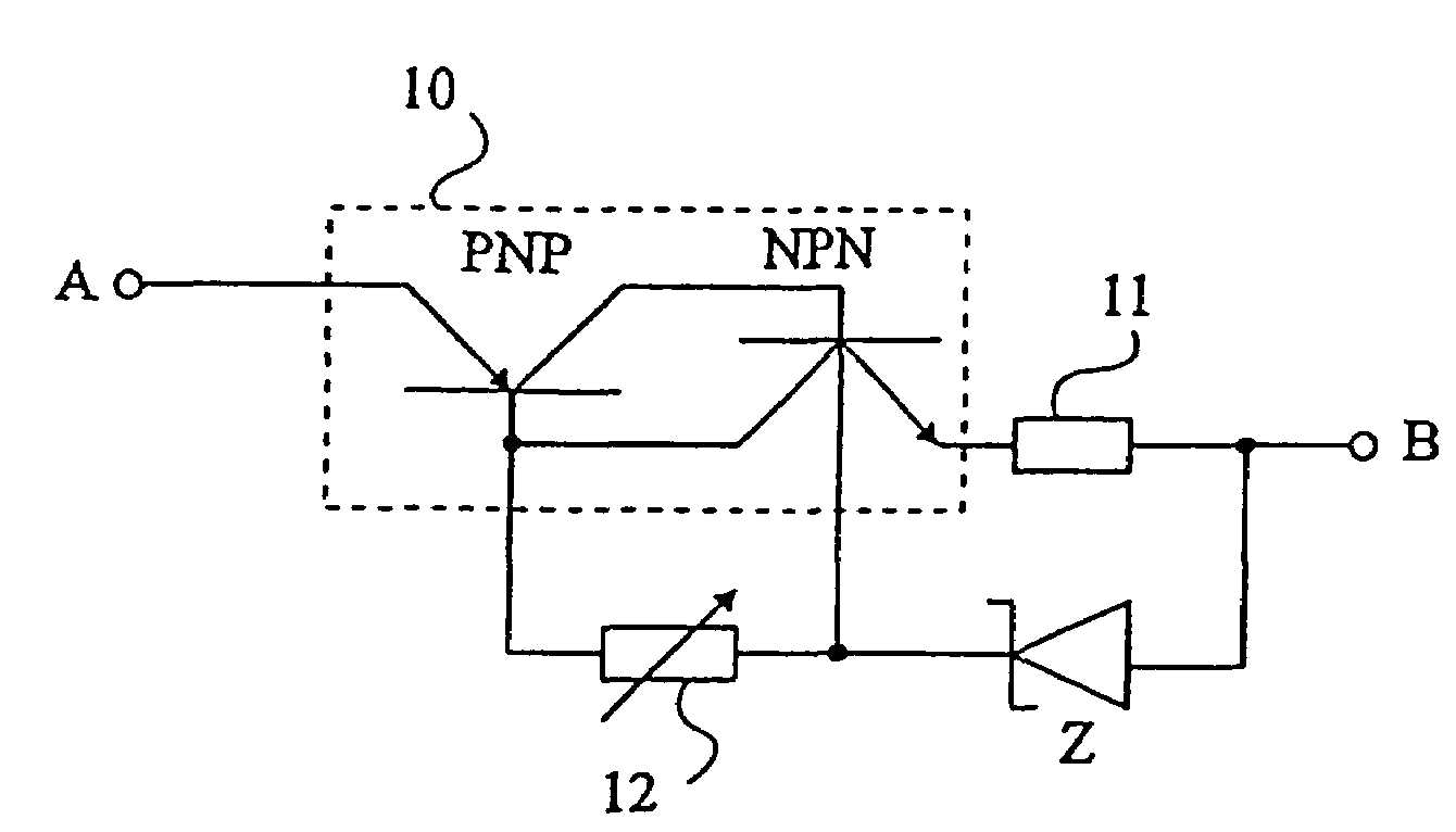
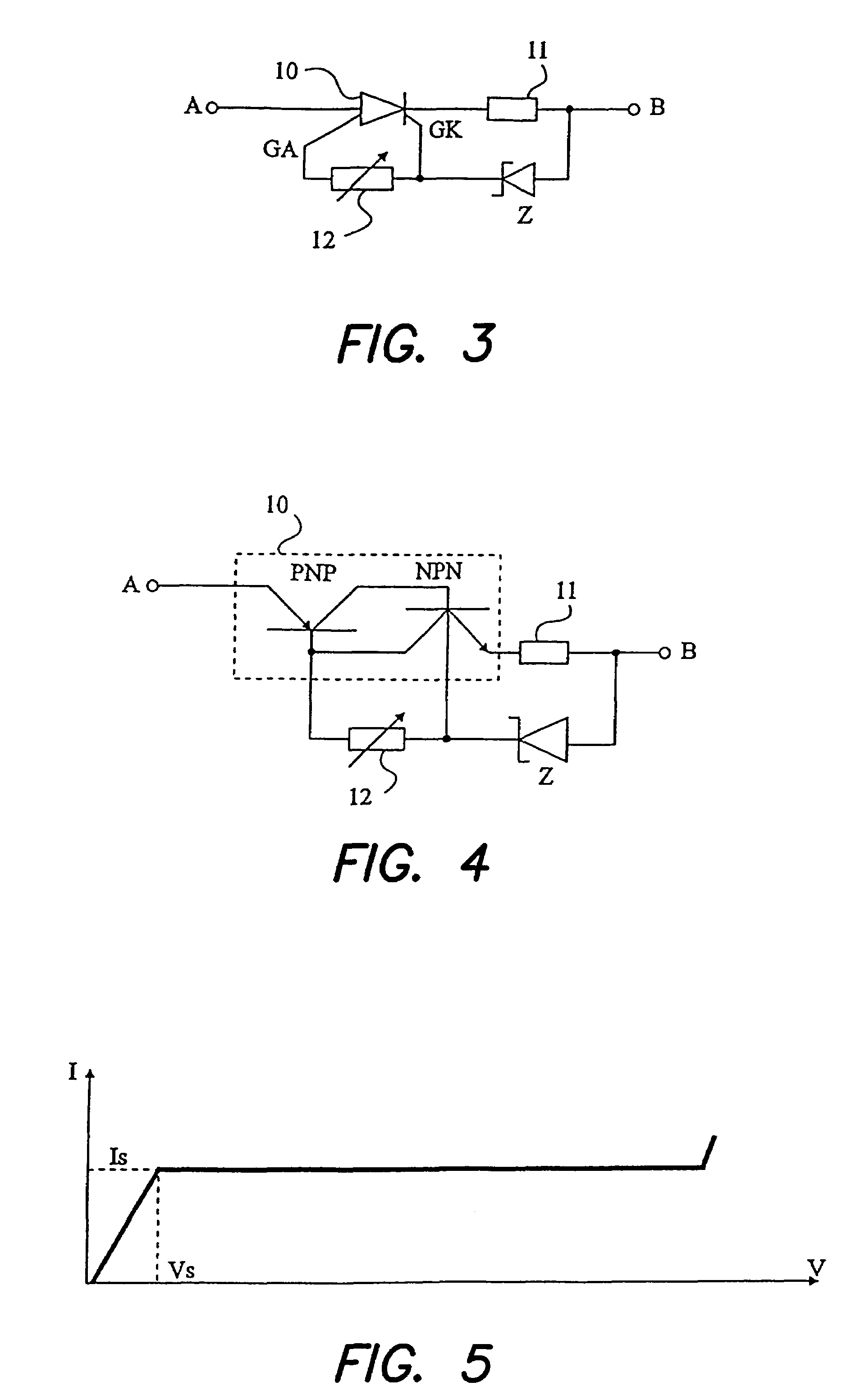
[0032]FIG. 3 shows the circuit of a current generator according to the present invention. It includes between terminals A and B a gate turn-off thyristor (GTO) 10 provided with an anode gate and a cathode gate. This GTO thyristor is connected by its anode to terminal A and by its cathode to the first terminal of a resistor 11, the second terminal of which is connected to terminal B. A current limiting element 12 is inserted between anode gate GA and cathode gate GK of thyristor 10. An avalanche diode Z is connected by its cathode to cathode gate GK of thyristor 10 and by its anode to terminal B.

[0033]Thus, when the device is in operation, the current in resistor 11 or cathode current of thyristor 10 is equal to (Vz-Vbe) / R, R being the value of resistor 11 and Vbe designating a voltage drop between the cathode gate and the thyristor cathode. Although it has been illustrated that the reference voltage function is ensured by an avalanche diode Z, it should be noted that this function c...


PUM


Abstract

A constant current generator connected between first and second terminals includes a gate turn-off thyristor in series with a resistor; a current limiting component connected between the anode gate and the cathode gate of the thyristor; and a voltage reference connected between the cathode and the cathode gate of the thyristor.

Description

BACKGROUND OF THE INVENTION[0001]1. Field of the Invention[0002]The present invention relates to current limiters or generators, and more specifically to current limiters likely to be inserted in power circuits to which high voltages, for example, above one hundred volts, can be applied.[0003]2. Discussion of the Related Art[0004]A current limiter is a component arranged in series in a circuit and intended for limiting the current in the circuit to a constant value. Thus, a current limiter is also often called a current generator.[0005]Among current limiters or generators, one of the best known is formed of a depletion MOS transistor having its gate connected to its source. Such a component has the following disadvantages:[0006]it incorporates an intrinsic diode in anti-parallel and thus cannot withstand reverse voltages;[0007]it is technologically difficult to adjust the parameters which set the limiting current, especially the threshold voltage of the MOS transistor and the resist...

Claims


Application Information

Patent Timeline
IPC IPC(8): H02H9/00H02H1/00H01L29/74
CPCH01L29/74
Inventor PEZZANI, ROBERT
Owner STMICROELECTRONICS SRL
Why Eureka
Try Eureka