Acoustic source localization system and applications of the same

a source localization and source technology, applied in direction finders, instruments, acoustic wave reradiation, etc., can solve the problems of limiting the coverage efficiency in dense urban terrain, unsatisfactory performance of acoustic source localization in urban environments, etc., to eliminate erroneous measurements and multi-path effects

Active Publication Date: 2008-10-07
VANDERBILT UNIV
View PDF6 Cites 33 Cited by
  • Summary
  • Abstract
  • Description
  • Claims
  • Application Information

AI Technical Summary

Benefits of technology

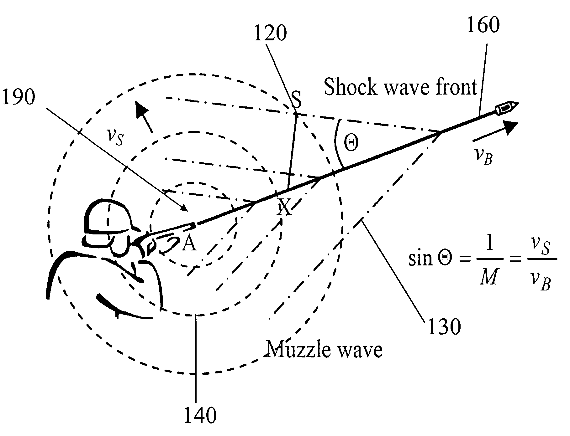
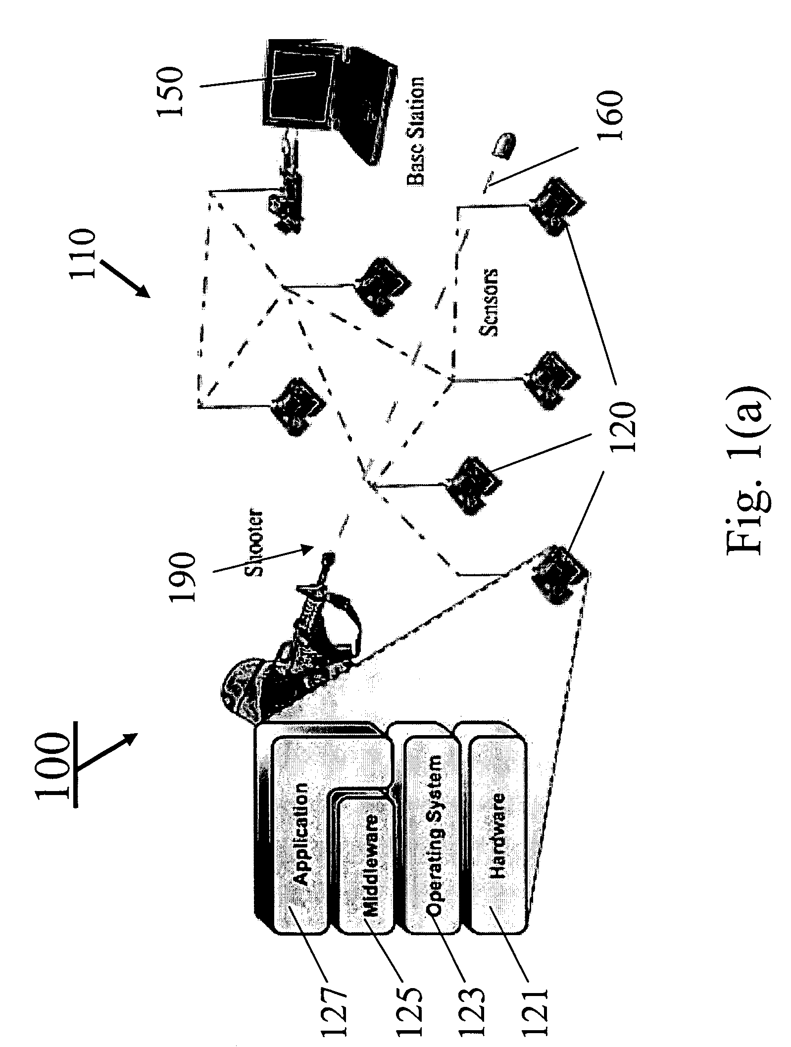
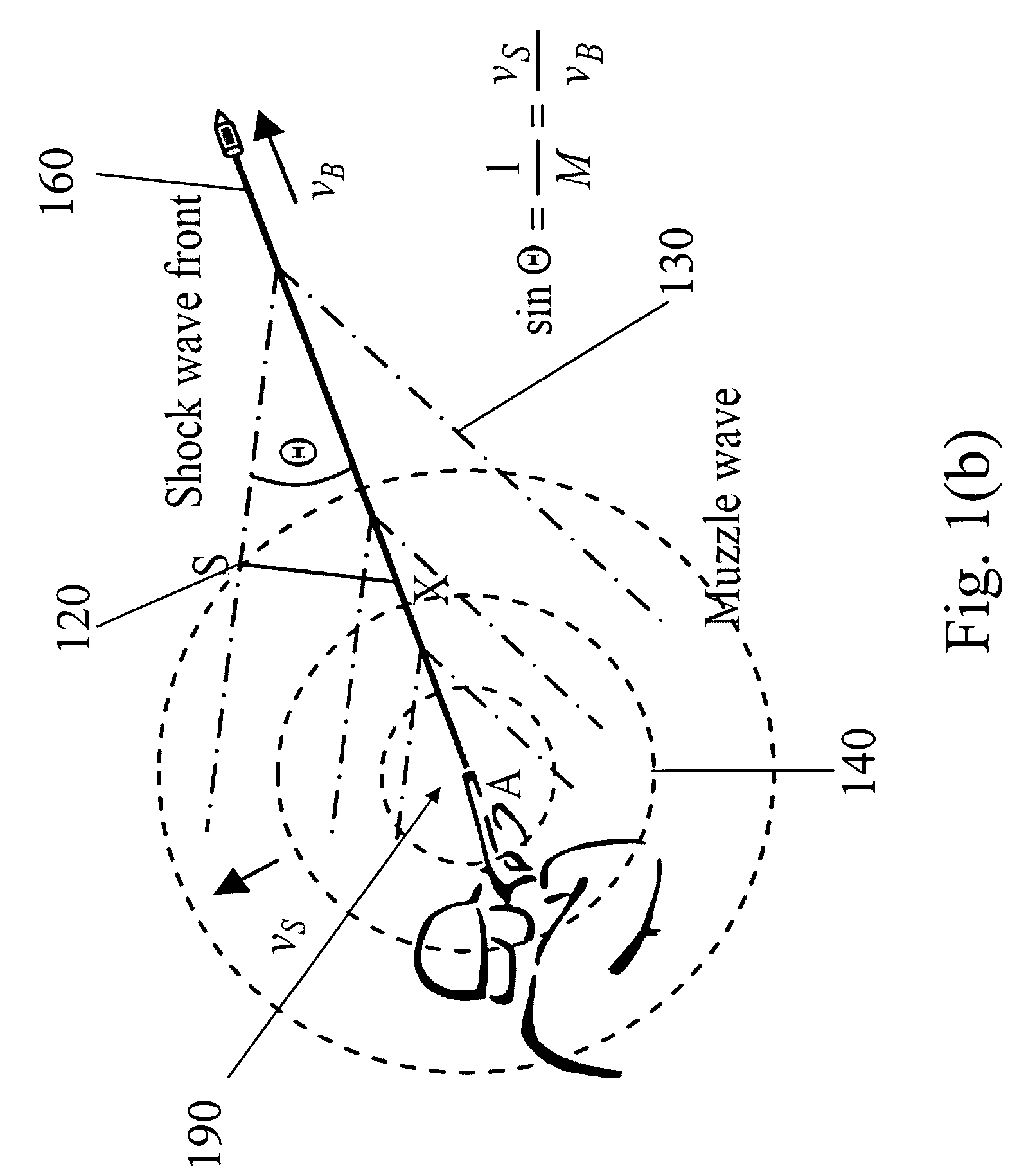
[0016]Additionally, the method comprises the steps of receiving the broadcasted information of the acoustic waves from the sensor network by the base station, and processing the received information of the acoustic waves so as to locate the acoustic source of the acoustic event in the base station. In one embodiment, the processing step is performed with a sensor fusion algorithm. The sensor fusion algorithm comprises the steps of defining a consistency function from the obtained information of the acoustic waves and positions of the corresponding sensor nodes finding a maximum of the consistency function, and identifying a location of the maximum of the consistency function as the location of the acoustic source of the acoustic event. The consistency function is configured such that the consistency function automatically classifies and eliminates erroneous measurements and multi-path effects.

Problems solved by technology

Acoustic source localization is a well-studied problem.
However, their performance in urban environments is usually unsatisfactory.
This significantly limits the coverage efficiency in a dense urban terrain.
Furthermore, the environmental conditions associated with active warfare, or even typical peacetime urban noise, aggravate the problem.
They do not perform well in urban environments.
If some of the limited number of sensors do not have direct line of sight, they will not detect the shot.
In case of the acoustic systems, the problem becomes much harder due to multi-path effects.
Instead of missing a shot, they may pick up echoes resulting in an erroneous location estimate.
Therefore, a heretofore unaddressed need exists in the art to address the aforementioned deficiencies and inadequacies.

Method used


Image

  • Acoustic source localization system and applications of the same
  • Acoustic source localization system and applications of the same
  • Acoustic source localization system and applications of the same

Examples


Embodiment Construction

[0027]The present invention is more particularly described in the following examples that are intended as illustrative only since numerous modifications and variations therein will be apparent to those skilled in the art. Various embodiments of the invention are now described in detail. Referring to the drawings FIGS. 1-6, like numbers indicate like components throughout the views. As used in the description herein and throughout the claims that follow, the meaning of “a”, “an”, and “the” includes plural reference unless the context clearly dictates otherwise. Also, as used in the description herein and throughout the claims that follow, the meaning of “in” includes “in” and “on” unless the context clearly dictates otherwise. Moreover, titles or subtitles may be used in the specification for the convenience of a reader, which shall have no influence on the scope of the present invention. Additionally, some terms used in this specification are more specifically defined below.

Definiti...


PUM


Abstract

A system for locating an acoustic source from an acoustic event of the acoustic source. In one embodiment, the system includes a sensor network having a plurality of spatially separated sensor nodes each located in a predetermined position encountering acoustic waves generated by an acoustic event passing proximate to the plurality of spatially separated sensor nodes, where the plurality of spatially separated sensor nodes are synchronized to a common time base such that when the acoustic event is detected, information of the acoustic waves from each of the plurality of spatially separated sensor nodes is obtained and broadcasted through the sensor network. The system further includes a base station for receiving information of the acoustic waves broadcasted from the sensor network and processing the received information of the acoustic waves so as to locate the acoustic source of the acoustic event.

Description

CROSS-REFERENCE TO RELATED PATENT APPLICATION[0001]This application claims the benefit, pursuant to 35 U.S.C. §119(e), of U.S. provisional patent application Ser. No. 60 / 610,310, filed Sep. 16, 2004, entitled “AN ACOUSTIC SOURCE LOCALIZATION SYSTEM AND APPLICATIONS OF THE SAME,” by Akos Ledeczi, Miklos Maroti, Gyula Simon and Gyorgy Balogh, which is incorporated herein by reference in its entirety.[0002]Some references, which may include patents, patent applications and various publications, are cited and discussed in the description of this invention. The citation and / or discussion of such references is provided merely to clarify the description of the present invention and is not an admission that any such reference is “prior art” to the invention described herein. All references cited and discussed in this specification are incorporated herein by reference in their entireties and to the same extent as if each reference was individually incorporated by reference. In terms of notat...

Claims


Application Information

Patent Timeline
Patent Type & Authority Patents(United States)
IPC IPC(8): G01S3/80
CPCG01S5/0081G01S5/22Y10S367/906
Inventor LEDECZI, KOSMAROTI, MIKLOSSIMON, GYULABALOGH, GYORGY
Owner VANDERBILT UNIV
Why Eureka
Try Eureka