Supercharge Your Innovation With Domain-Expert AI Agents!

Automatic dispersion compensation device and compensation method

a compensation device and automatic technology, applied in the field of optical communication systems, can solve the problems of difficult to realize highly accurate chromatic dispersion compensation, and further limiting the transmission distance of optical signals, so as to improve system performance, influence communication quality, and optimize the control of chromatic dispersion

Inactive Publication Date: 2008-10-07
FUJITSU LTD
View PDF16 Cites 15 Cited by
  • Summary
  • Abstract
  • Description
  • Claims
  • Application Information

AI Technical Summary

Benefits of technology

[0056]According to the present invention, optimal control of chromatic dispersion in a transmission line can be exercised in order to influence communication quality using a general-purpose transmission quality monitor instead of a special dispersion monitor, and system performance can thus be improved.

Problems solved by technology

However, since in such an ultra-high-speed optical communication system, the influence on the transmission quality, that is, transmission waveform degradation due to chromatic dispersion and polarization-mode dispersion, increases, thus limiting the transmission distance of optical signals, which is a problem.
On the other hand, since the distance between repeaters and the chromatic dispersion value of an optical fiber transmission line possessed by a communication carrier are not accurately known, it is often difficult to realize highly accurate chromatic dispersion compensation using a fixed-chromatic dispersion compensation method adopting a dispersion compensated fiber (DCF) and the like.
In reality, since components causing polarization-mode dispersion, such as an optical amplifier, a chromatic dispersion compensator and the like, must be installed in the transmission line of an optical communication system, there is a possibility that the transmission distance of an optical signal will be further limited.
As described above, chromatic dispersion and polarization-mode dispersion are major factors for limiting the performance of an optical communication system.
However, in order to be able always to measure chromatic dispersion without communication quality degradation during the system operation, (1) one set of chromatic dispersion measuring instruments is needed for each repeater section and (2) the measurement of light with a wavelength different from that of the data signal must be wavelength-multiplexed, both of which are problems.
It is not practical from the viewpoints of economical efficiency and device size to realize such measures.
A polarization dispersion monitor monitoring a specific frequency element of an incoming signal is also proposed although it is difficult to apply it in an environment where there is chromatic dispersion.
Therefore, it is difficult to realize an automatic dispersion compensator simultaneously compensating for both chromatic dispersion and polarization-mode dispersion.
Furthermore, if an already-proposed parameter indicating transmission quality, such as an error rate and the like, is used instead of a chromatic dispersion monitor, it is difficult to separate the degradation of transmission quality due to chromatic dispersion from that due to factors other than it.
However, since there are various factors of transmission quality degradation, having only a chromatic dispersion compensator means that it cannot always compensate for all transmission quality degradation.
Therefore, there is no guarantee that optimal control can be always exercised, and furthermore sometimes there will be no control.
If in this way, a chromatic dispersion compensator is operated without separating the factors of transmission quality degradation, optimal control cannot be guaranteed and sometimes there is no control.
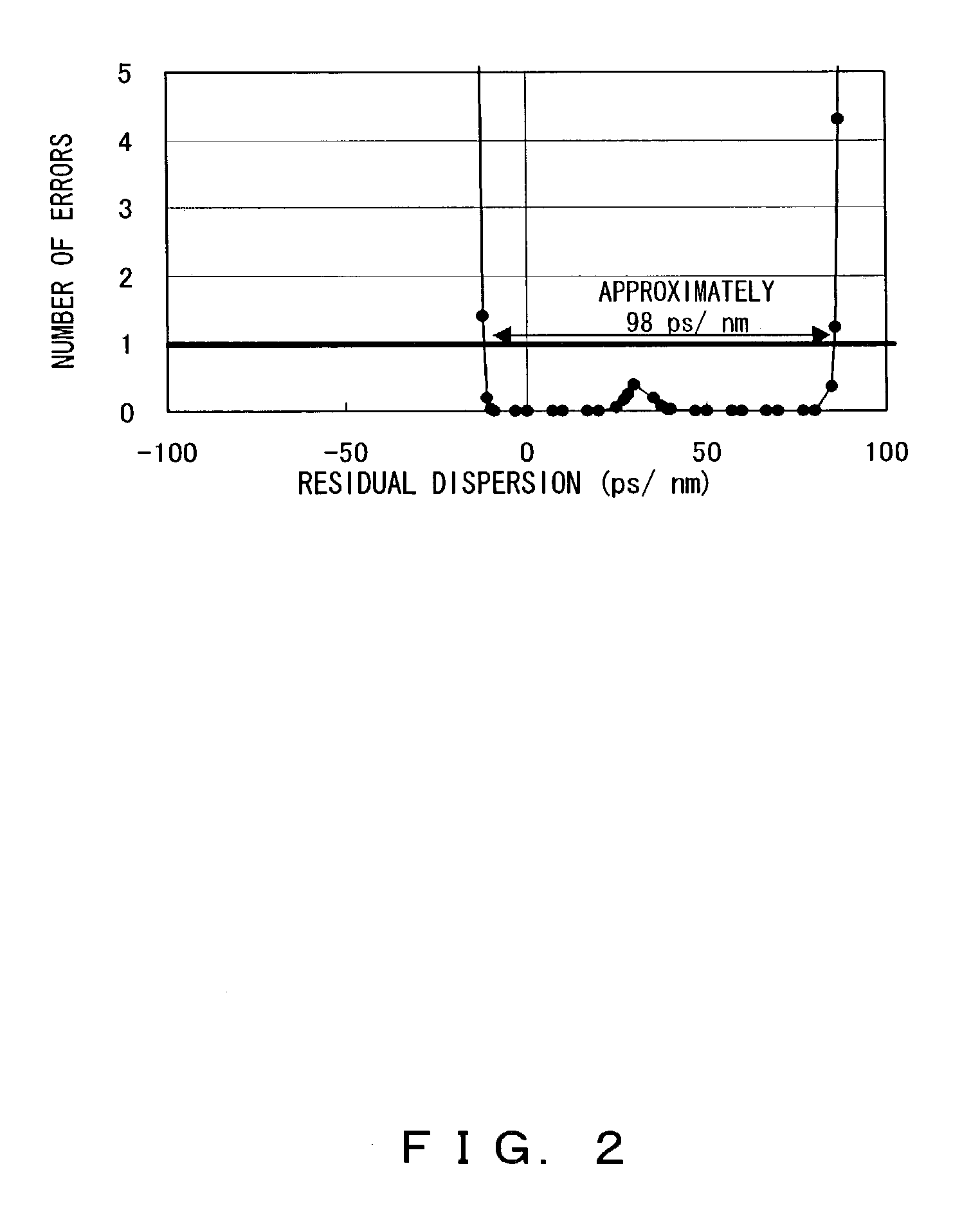
Compared with FIG. 2, in FIG. 3, there is no control and it is difficult to detect an optimal chromatic dispersion value.
In other words, in such a situation, the control of only a dispersion compensator cannot realize a transmission that matches the allowable number of errors.
Therefore, in order to control a chromatic dispersion compensator using a transmission quality monitor, the factors causing transmission quality degradation must be separated, which is a problem.

Method used


Image

  • Automatic dispersion compensation device and compensation method
  • Automatic dispersion compensation device and compensation method
  • Automatic dispersion compensation device and compensation method

Examples


Embodiment Construction

[0111]The preferred embodiments of the present invention are described below with reference to the drawings.

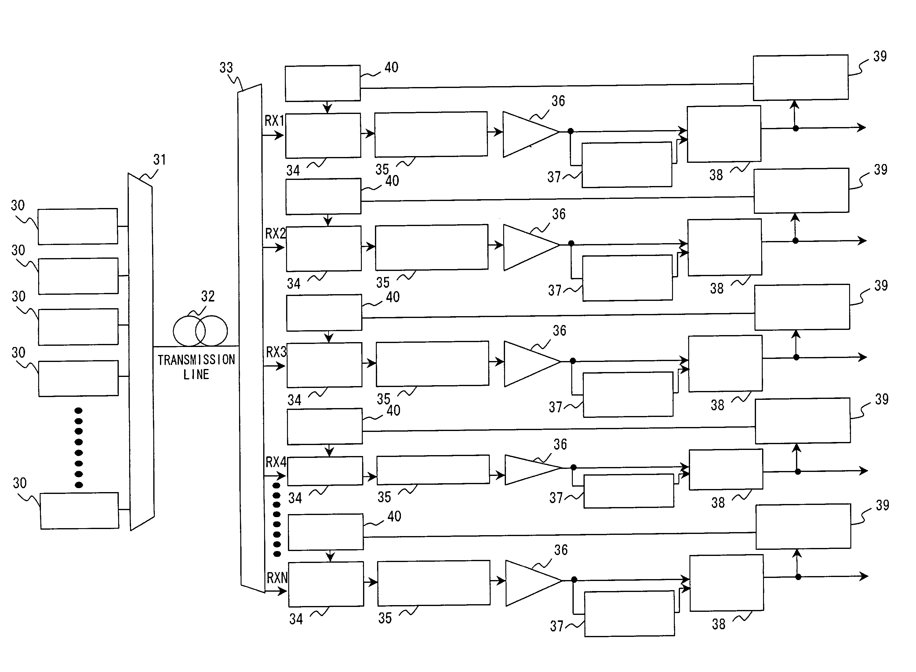
[0112]In FIG. 4, an automatic dispersion compensation device 1 comprises a transmission quality measurement unit 2 and a chromatic dispersion compensation amount control unit. The transmission quality measurement unit 2 measures the transmission quality of optical signals from one or more channels. The transmission quality measurement unit 2 is a transmission quality monitor measuring, for example, the Q-factor, that is, the error rate of an incoming optical signal, and the like.

[0113]In FIG. 4, an automatic dispersion compensation device 1 comprises a transmission quality measurement unit 2 and a chromatic dispersion compensation amount control unit. The transmission quality measurement unit 2 measures the transmission quality of optical signals from one or more channels. The transmission quality measurement unit 2 is a transmission quality monitor measuring, for example, the...


PUM


Abstract

The automatic dispersion compensation device of the present invention comprises a unit measuring the transmission quality of incoming optical signals for one or more channels input from a transmission line and a unit separating and detecting the transmission quality degradation due to chromatic dispersion, in the measurement result of the unit from degradation due to other factors and controlling a variable chromatic dispersion compensator (VDC) in such a way as to compensate for that degradation.

Description

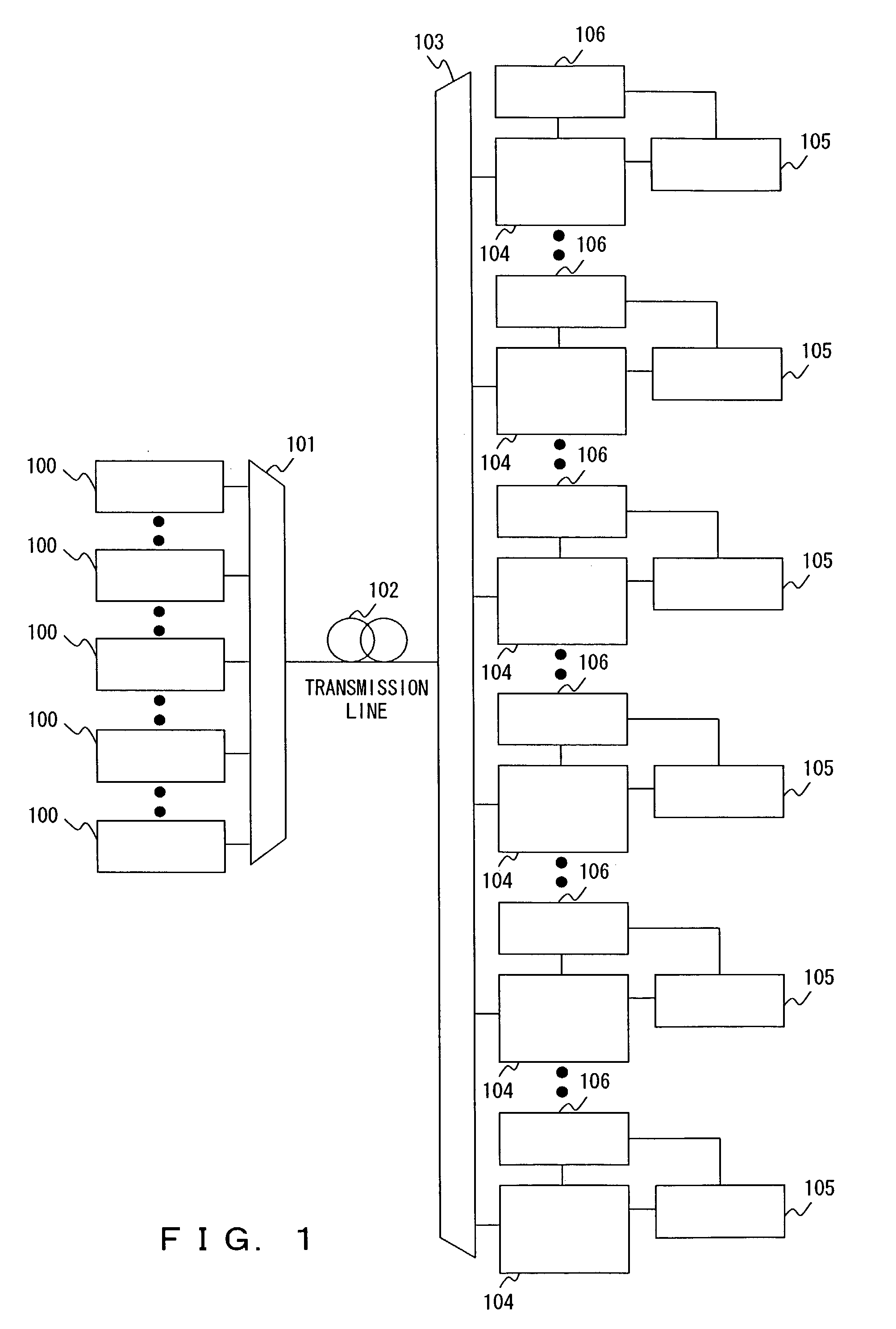
BACKGROUND OF THE INVENTION[0001]1. Field of the Invention[0002]The present invention relates to an optical communication system, and more specifically, it relates to a chromatic dispersion compensation technology as an indispensable technology for realizing an ever-progressing large-capacity, high-speed and long-haul optical communication system. In particular, it relates to an automatic dispersion compensation device optimally compensating for chromatic dispersion and polarization-mode dispersion in a transmission line and a compensation method thereof.[0003]2. Description of the Related Art[0004]Recently, although the network capacity has increased rapidly, demand for an even larger capacity of the network has also been grown. Although currently a wavelength division multiplexing (WDM) optical communication method based on a transfer rate of 10 Gb / s per channel is already put into practical use, a far larger capacity is needed in the future. In these situations, the improvement o...

Claims


Application Information

Patent Timeline
IPC IPC(8): H04J14/02H04B10/2507H04B10/07H04B10/2519H04B10/2525
CPCH04B10/25133H04B10/2572
Inventor TAKAHARA, TOMOOOOI, HIROKIISHIKAWA, GEORGE
Owner FUJITSU LTD
Features
  • R&D
  • Intellectual Property
  • Life Sciences
  • Materials
  • Tech Scout
  • Unparalleled Data Quality
  • Higher Quality Content
  • 60% Fewer Hallucinations
Learn More