Hydraulic fluid change indicating device for automatic transmission

a technology of automatic transmission and indicating device, which is applied in the direction of switch power arrangement, contact mechanism, instruments, etc., can solve the problems of affecting the lubricating operation, excessive use, and forgetting the periodic change of engine oil,

Inactive Publication Date: 2008-10-07
HONDA MOTOR CO LTD
View PDF5 Cites 19 Cited by
  • Summary
  • Abstract
  • Description
  • Claims
  • Application Information

AI Technical Summary

Benefits of technology

[0008]It is therefore an object of the present invention to provide a hydraulic fluid change indicating device for an automatic transmission for a vehicle which can suitably indicate a warning of changing a hydraulic fluid for the automatic transmission.
[0010]According to this aspect, the amount of heat generated in the torque converter of the automatic transmission is calculated, and the thermal deterioration rate based on the fluid temperature is corrected according to the heat amount calculated above. Accordingly, the accuracy of detection of the change time for the hydraulic fluid can be improved.
[0014]According to this aspect, the hydraulic fluid change threshold is set in consideration of the distance corresponding to the remaining service life of the hydraulic fluid. Accordingly, the change of the engine oil and the change of the hydraulic fluid can be performed simultaneously before the service life of the hydraulic fluid is ended, thereby improving the maintainability.

Problems solved by technology

However, such a periodic change of engine oil is apt to be forgotten.
If the engine oil or the hydraulic fluid for the transmission is used beyond an allowable deterioration degree, such an excess use may interfere with a lubricating operation.
However, the deterioration of the engine oil or the hydraulic fluid is dependent not only on the distance traveled or the period of time elapsed, but also largely on the use condition of a vehicle such as a road condition.
Therefore, it is unsuitable to warn on the basis of only the distance traveled or the period of time elapsed.
However, it is unsuitable to directly apply this lubricating oil change warning device to a hydraulic fluid change warning device for an automatic transmission.
Accordingly, if the lubricating oil change warning device described in the above publication is used as a hydraulic fluid change warning device for an automatic transmission, a suitable warning of changing the hydraulic fluid cannot be given because a parameter on the heat generation in the torque converter is not considered.

Method used


Image

  • Hydraulic fluid change indicating device for automatic transmission
  • Hydraulic fluid change indicating device for automatic transmission
  • Hydraulic fluid change indicating device for automatic transmission

Examples


Embodiment Construction

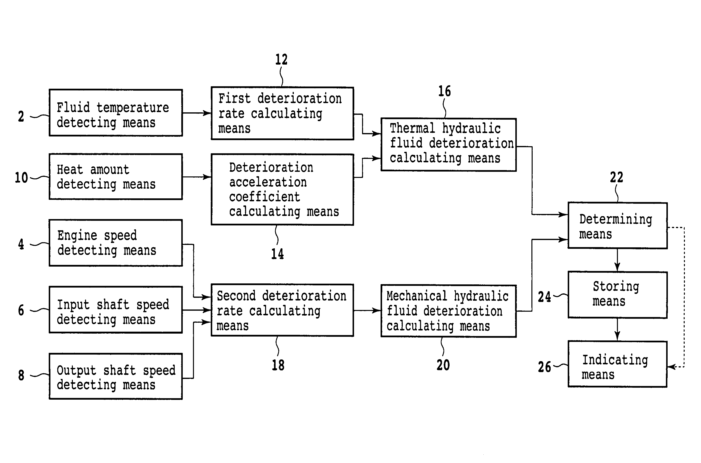
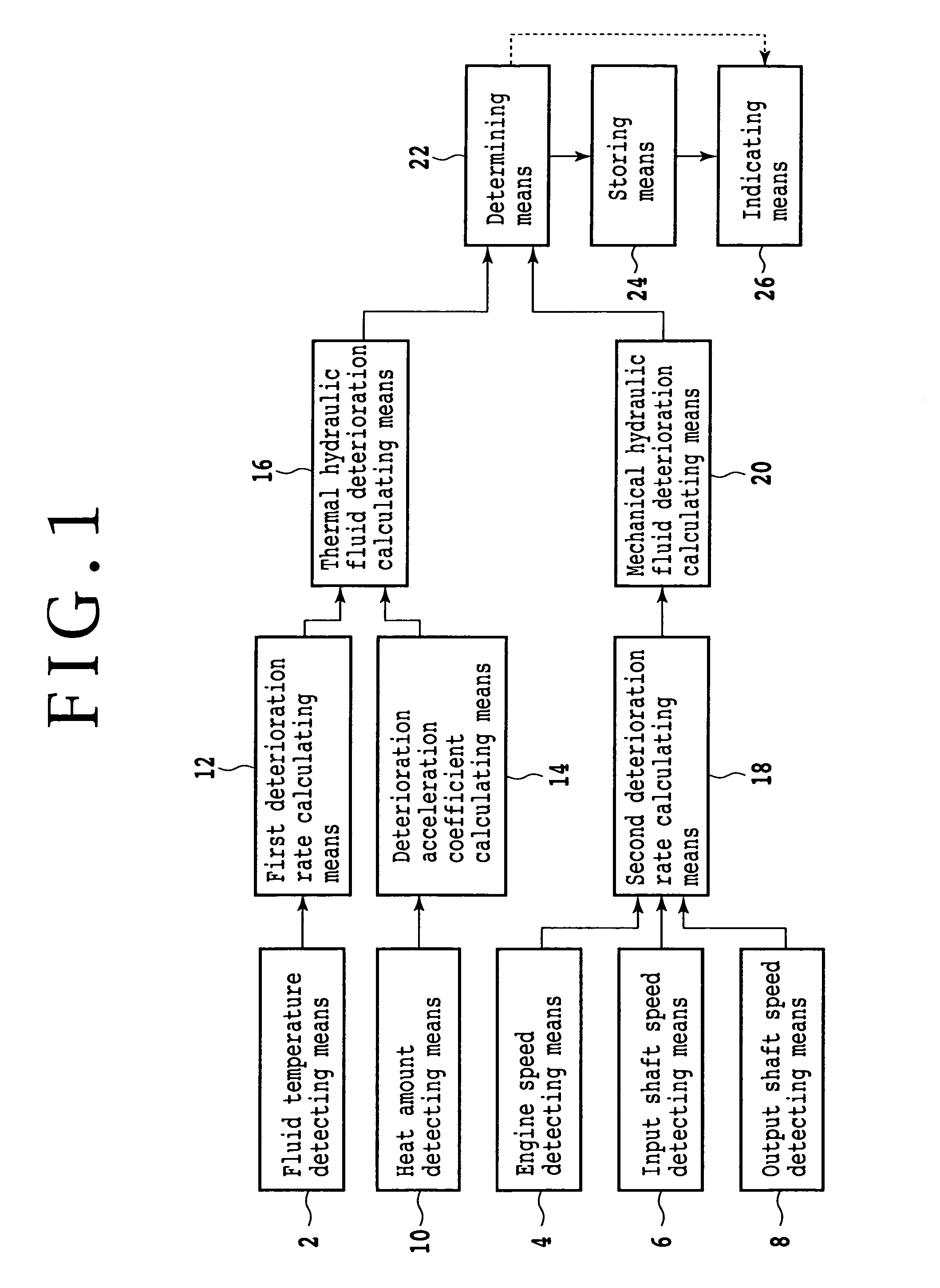
[0023]FIG. 1 is a block diagram showing a basic configuration of the present invention. The hydraulic fluid change indicating device for the automatic transmission according to the present invention includes fluid temperature detecting means 2 for detecting the temperature of a hydraulic fluid for the automatic transmission, engine speed detecting means 4 for detecting the rotational speed of an engine, input shaft speed detecting means 6 for detecting the rotational speed of an input shaft in the automatic transmission, output shaft speed detecting means 8, and heat amount detecting means 10 for detecting the amount of heat generated in a torque converter.

[0024]A first deterioration rate is obtained by first deterioration rate calculating means 12 according to the fluid temperature detected by the fluid temperature detecting means 2. A deterioration acceleration coefficient is obtained by deterioration acceleration coefficient calculating means 14 according to the heat amount detec...


PUM

PropertyMeasurementUnit
temperatureaaaaaaaaaa
rotational speedaaaaaaaaaa
deterioration acceleration coefficientaaaaaaaaaa

Abstract

A hydraulic fluid change indicating device for an automatic transmission includes a first deterioration rate calculating unit; a deterioration acceleration coefficient calculating unit; and a thermal hydraulic fluid deterioration calculating unit for calculating a thermal hydraulic fluid deterioration according to the first deterioration rate and the deterioration acceleration coefficient. The device further includes a second deterioration rate calculating unit according to an engine speed, input shaft speed, and output shaft speed; a mechanical hydraulic fluid deterioration calculating unit for calculating a mechanical fluid deterioration according to the second deterioration rate; and a determining unit for determining whether or not the thermal hydraulic fluid deterioration or the mechanical hydraulic fluid deterioration is greater than a predetermined hydraulic fluid change threshold.

Description

BACKGROUND OF THE INVENTION[0001]1. Field of the Invention[0002]The present invention relates to a hydraulic fluid change indicating device for an automatic transmission for a vehicle which can suitably indicate a warning of changing a hydraulic fluid for the automatic transmission.[0003]2. Description of the Related Art[0004]An engine oil used for lubrication of an engine for a vehicle and a hydraulic fluid used for lubrication of a transmission deteriorate with the elapse of time. Therefore, it is necessary to change the engine oil and the hydraulic fluid for the transmission. For example, it is recommended in an operation manual to change the engine oil every time a fixed distance is traveled or a fixed period is passed. The time of such engine oil change is shown by attaching a label at an easy-to-see place. However, such a periodic change of engine oil is apt to be forgotten.[0005]If the engine oil or the hydraulic fluid for the transmission is used beyond an allowable deterior...

Claims


Application Information

Patent Timeline
Patent Type & Authority Patents(United States)
IPC IPC(8): G06F7/00F16H57/04G01N33/28G06F17/00
CPCF16H57/0405G01N33/2888Y10T477/653Y10T477/60Y10T477/619
Inventor INAGAWA, YASUSHIFURUMOTO, MITSUMASAKOYAMA, HIDEOTAKAGI, YOSHIARI
Owner HONDA MOTOR CO LTD
Why Eureka
Try Eureka