Arrangement in recovery boiler

a technology for recovery boilers and recovery boilers, applied in steam superheaters, steam boiler components, lighting and heating apparatus, etc., can solve problems such as not always possible, and achieve the effect of increasing the heat transfer surface of the superheaters

Active Publication Date: 2008-10-14
KVAERNER POWER OY
View PDF16 Cites 22 Cited by
  • Summary
  • Abstract
  • Description
  • Claims
  • Application Information

AI Technical Summary

Benefits of technology

[0008]An advantage of the invention is that in this way the heat transfer surface of the superheaters is increased without having to enlarge the so-called superheater region in the uppermost part of the boiler. The invention allows achieving more easily than the current known solutions the high temperature and pressure values of the steam.
is that in this way the heat transfer surface of the superheaters is increased without having to enlarge the so-called superheater region in the uppermost part of the boiler. The invention allows achieving more easily than the current known solutions the high temperature and pressure values of the steam.

Problems solved by technology

This is not always possible, for instance owing to corrosion.

Method used


Image

  • Arrangement in recovery boiler
  • Arrangement in recovery boiler
  • Arrangement in recovery boiler

Examples


Embodiment Construction

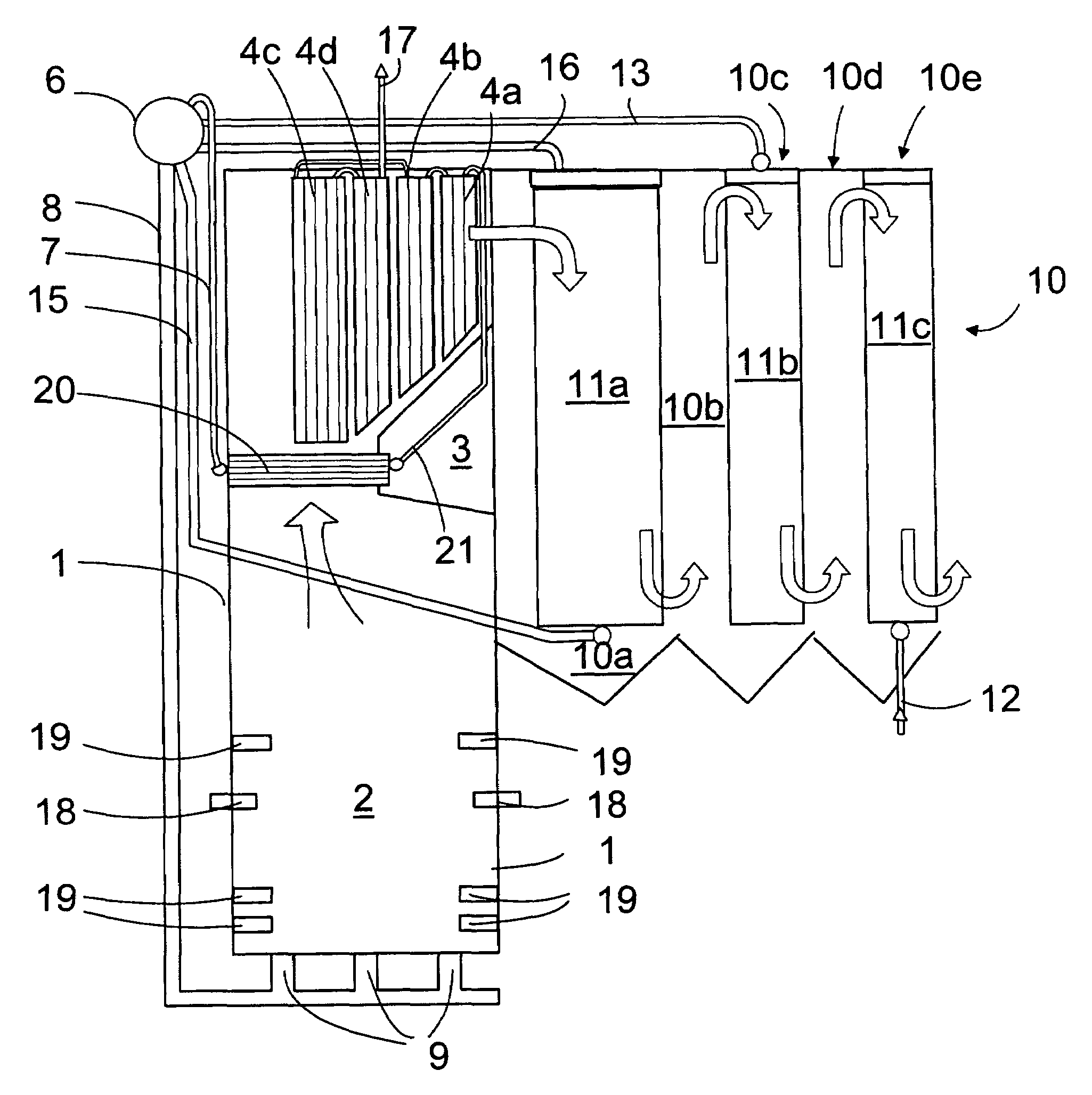
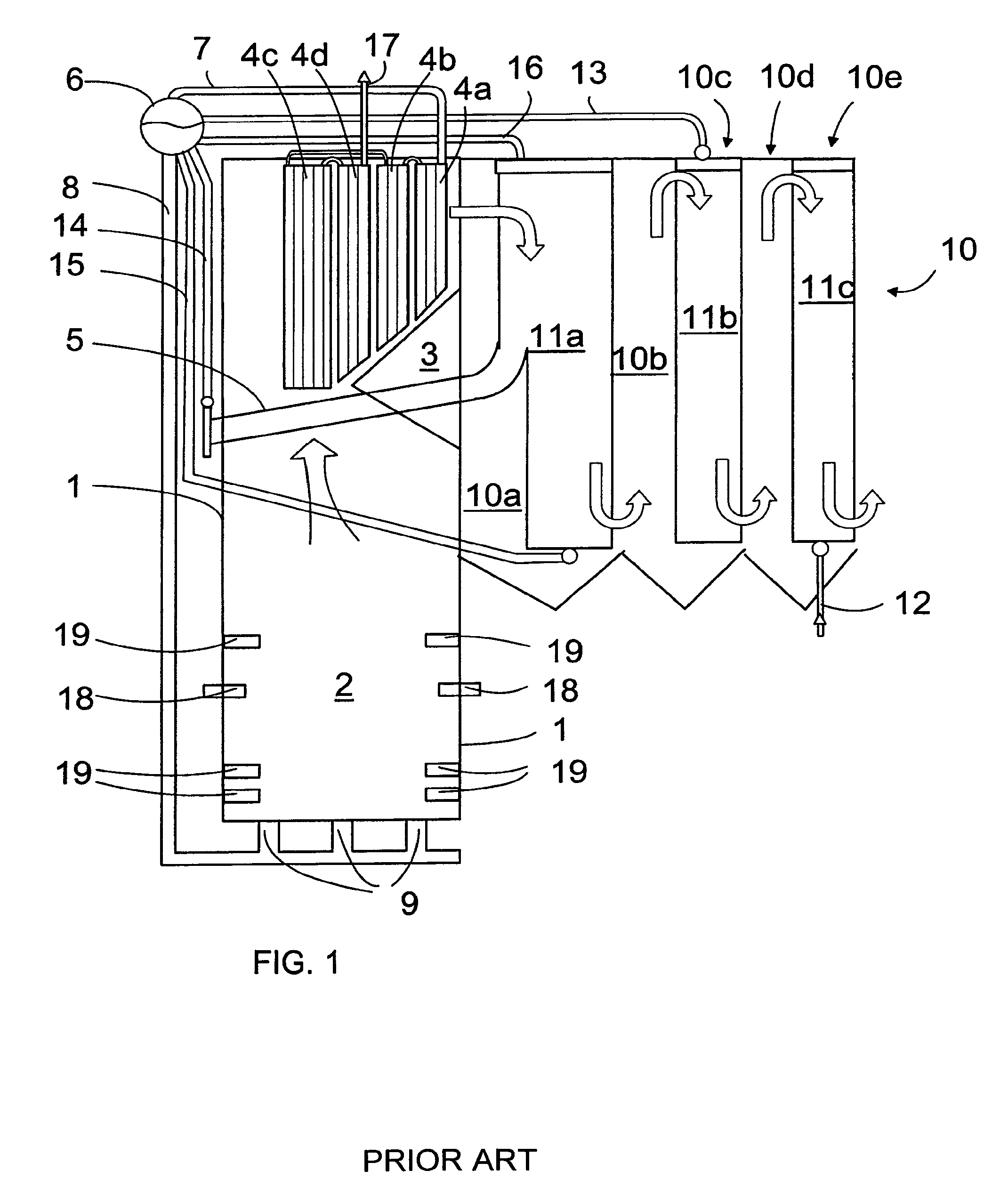
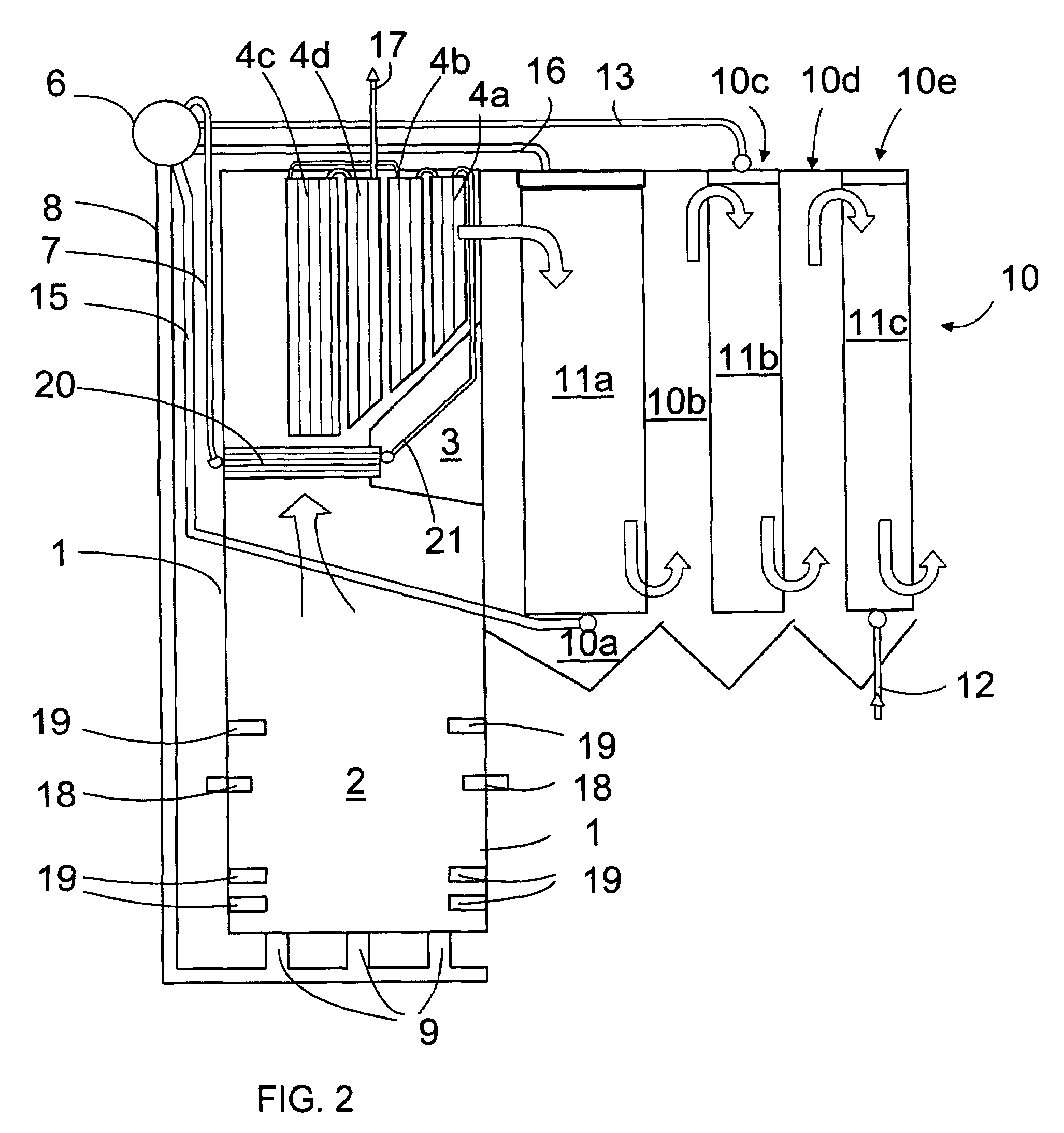
[0012]FIGS. 1 and 2 schematically show a vertical side view in cross-section of a recovery boiler. In both Figures the same numerals are used for corresponding components and they will not be specified separately later, if it is not necessary for understanding the solution in question.

[0013]The recovery boiler comprises walls 1, which are formed of tubes welded in a manner known per se. A furnace 2 remains inside the walls, and the upper part of the furnace is provided with a nose 3 for appropriately guiding the flue gas flows. Superheaters 4a-4d formed of tubes are placed above the nose 3 in the upper part of the recovery boiler. The superheaters 4a-4d are elements formed of several parallely located vertical tubes. Several such elements are placed in parallel in the transverse direction of the recovery boiler. Steam flows in the superheaters 4a-4d that is heated when hot flue gases heat the tubes from the outside. Currently screen tubes 5 are typically placed below the superheater...


PUM

PropertyMeasurementUnit
heat energyaaaaaaaaaa
heataaaaaaaaaa
pressureaaaaaaaaaa

Abstract

The invention relates to an arrangement in a recovery boiler, into which spent liquor to be combusted and combustion air are fed, the arrangement comprising superheaters in the upper part of the recovery boiler for recovering heat. Instead of screen tubes the invention is provided with a superheater formed of horizontal elements.

Description

BACKGROUND OF THE INVENTION[0001]The invention relates to an arrangement in a recovery boiler, into which spent liquor to be combusted and combustion air are fed, the arrangement comprising superheaters in the upper part of the recovery boiler for recovering heat.[0002]In a recovery boiler of a pulp mill the black liquor formed during the manufacturing of pulp is combusted such that on one hand heat energy is recovered and on the other hand chemicals are recovered, which can be returned to the process taking place in the pulp mill. Heat is generated in the furnace during combustion and is recovered utilizing walls and other heat transfer surfaces. The heat transfer surfaces are connected together in different ways so that both the recovery boiler and a flue gas duct placed thereafter are provided with different heat transfer surfaces, such as boiler banks and economizers, to allow cold water to heat and further to evaporate and finally the saturated vapour is heated in the superheat...

Claims


Application Information

Patent Timeline
Patent Type & Authority Patents(United States)
IPC IPC(8): F22G7/00D21CD21C11/12
CPCD21C11/12Y02P70/10
Inventor RAUKOLA, ANTTIMANTYNIEMI, JUSSI
Owner KVAERNER POWER OY
Why Eureka
Try Eureka