Eureka AIR delivers breakthrough ideas for toughest innovation challenges, trusted by R&D personnel around the world.

Cavity positioning tool and method

a technology for positioning tools and cavities, applied in the field of cavity positioning tools, can solve the problems of inaccurate and inefficient positioning methods, clogging or vapor lock, and inability to meet the needs of the patient, so as to reduce the tendency of particulate matter to coalesce, reduce the tendency of clogging of the pump inlet, and minimize the effect of vapor lock

Inactive Publication Date: 2008-10-14
EFFECTIVE EXPLORATION
View PDF136 Cites 16 Cited by
  • Summary
  • Abstract
  • Description
  • Claims
  • Application Information

AI Technical Summary

Benefits of technology

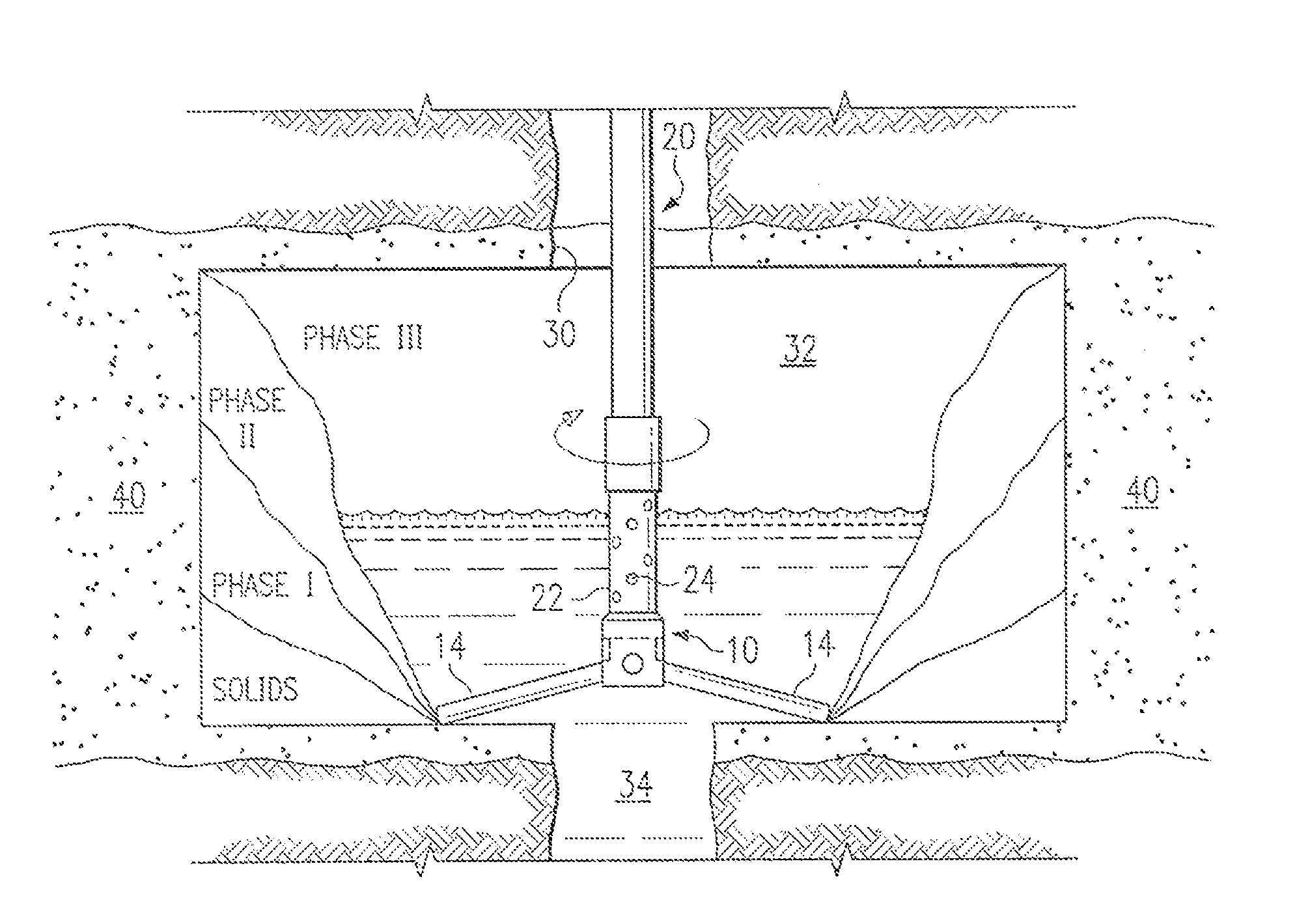
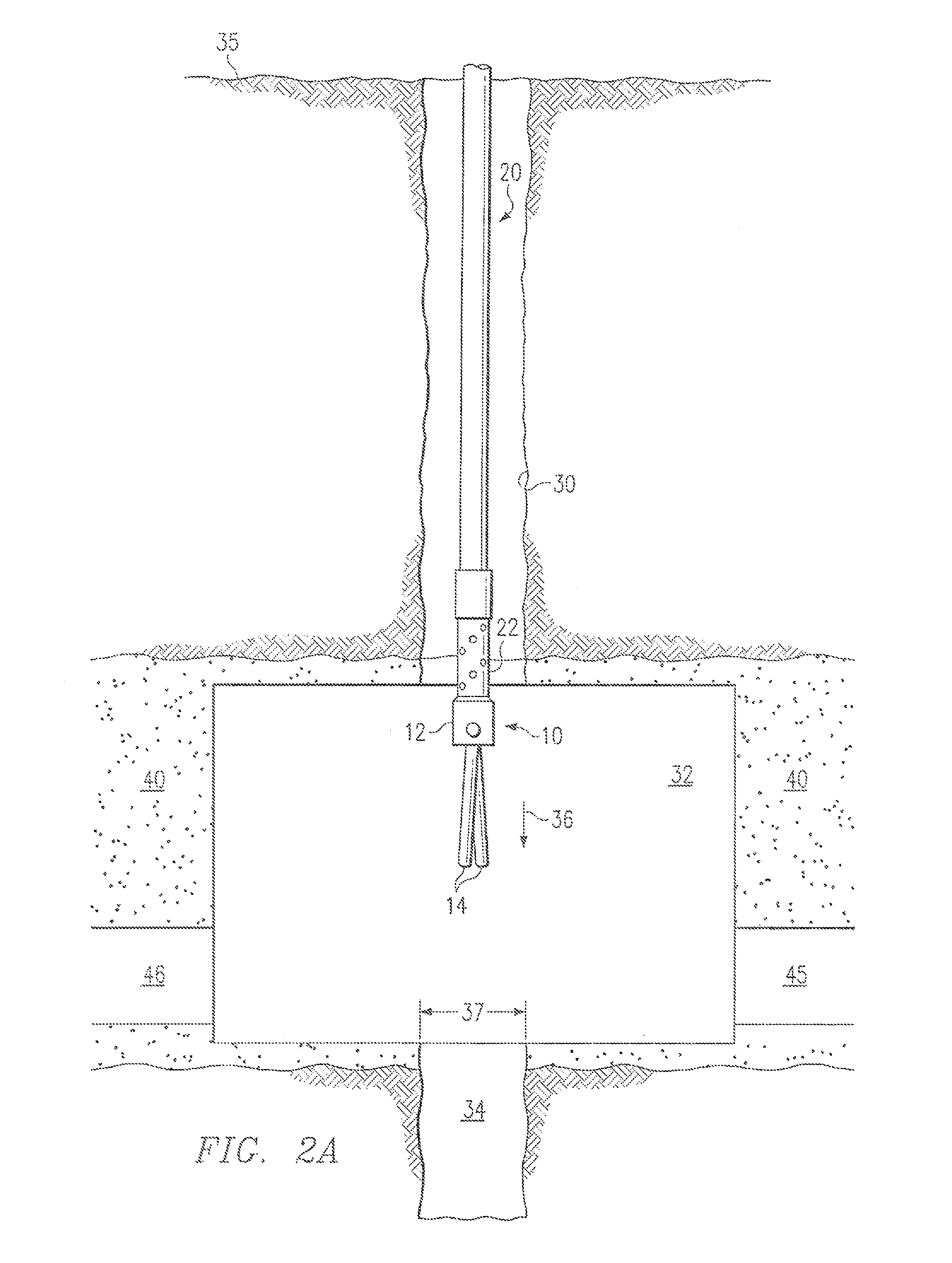
[0010]Another technical advantage of the present invention includes providing a method and system for positioning a pump inlet in a cavity. In particular, the pump inlet is positioned in a lower portion of the cavity by extending arms that rest on the cavity floor above a rat hole. This position of the pump inlet significantly reduces clogging of the pump inlets and prevents the pump from inadvertently entering the rat hole. Additionally, this position minimizes vapor lock.
[0011]Still another technical advantage of the present invention includes providing an improved method for supporting a pump string extended from the surface to a subterranean zone. In particular, a pump string is supported from the floor of the cavity. This allows well head maintenance and other surface operations to be performed without pulling out or otherwise supporting the string from the surface.
[0012]Still another technical advantage of the present invention includes providing an improved method for removing solid-laden fluids from a coal seam or other subterranean zone. In particular, a pump inlet is coupled to a cavity positioning device with extending arms that rest on a cavity floor above a rat hole. The arms are rotated slowly to agitate the liquid in the cavity, thereby suspending debris to allow removal within the liquid and lowering the tendency of particulate matter to coalesce. Thus, the debris and particulate matter is less likely to form clumps of larger particles, which reduces clogging of the pump inlets.
[0013]Other advantages are readily apparent to one skilled in the art from the following figures, descriptions, and claims.

Problems solved by technology

Traditional methods of positioning the pump inlets, however, are often inaccurate and inefficient, leading to clogging or vapor lock and increased maintenance and operation costs for the well.

Method used


Image

  • Cavity positioning tool and method
  • Cavity positioning tool and method
  • Cavity positioning tool and method

Examples


Embodiment Construction

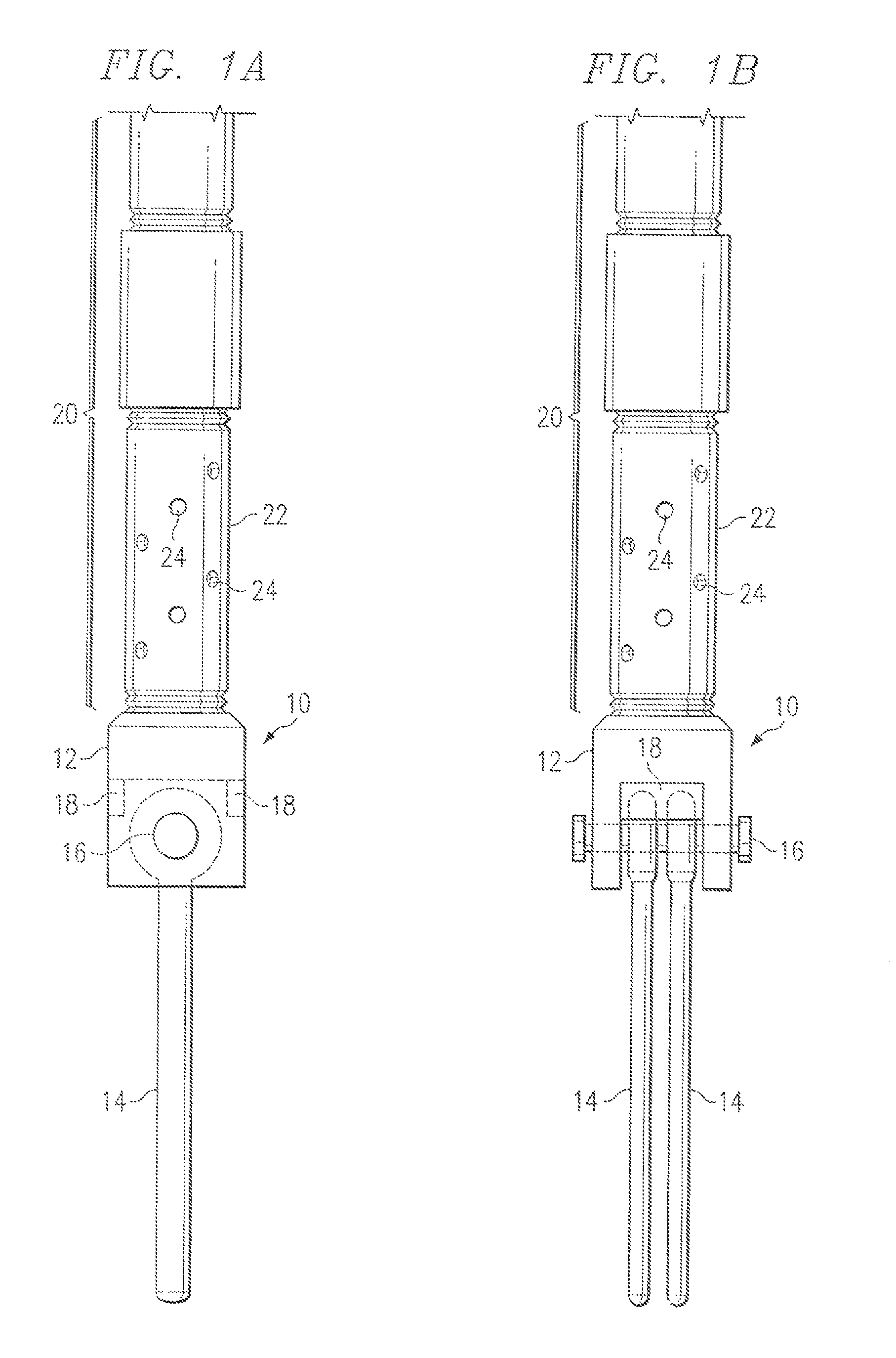
[0018]FIGS. 1A-B illustrate a cavity positioning tool 10 in accordance with one embodiment of the present invention. In this embodiment, tool 10 is adapted to position a pump inlet in a subsurface cavity. It will be understood that tool 10 may be adapted to position other suitable devices within or in relation to a cavity. For example, motors, controllers, and valves may be positioned in or relative to a cavity with the tool 10. Tool 10 is constructed of steel or other suitable metals or materials, such that are resistant to damage in the downhole environment.

[0019]Referring to FIG. 1A, the tool 10 comprises a head piece 12 and a plurality of blunt arms 14. As described in more detail below, the arms are coupled to the head piece 12 and operable to be radially extended outward from a first position of substantial alignment with a longitudinal axis associated with the head piece 12 to a second extended position. In the illustrated embodiment, the blunt arms 14 are coupled to head pie...


PUM


Abstract

In accordance with the teachings of the present invention, a method is provided for preventing formation of sludge in a subsurface cavity having particulate laden fluid disposed therein. The method includes positioning a downhole device having a fluid agitator into the fluid of the subsurface cavity and agitating the fluid using the fluid agitator.

Description

CROSS-REFERENCE TO RELATED APPLICATION[0001]This application is a continuation application of and claims priority to U.S. patent application Ser. No. 10 / 687,362, filed Oct. 14, 2003 now U.S. Pat. No. 7,213,644 by Joseph A. Zupanick, and entitled “Cavity Positioning Tool and Method”, which is a divisional of now abandoned U.S. patent application Ser. No. 10 / 188,159, filed Jul. 1, 2002, by Joseph A. Zupanick, entitled “Cavity Positioning Tool and Method”, which is a continuation of U.S. patent application Ser. No. 09 / 632,273, filed Aug. 3, 2000 by Joseph A. Zupanick, entitled “Cavity Positioning Tool and Method”, now U.S. Pat. No. 6,412,556.TECHNICAL FIELD OF INVENTION[0002]This invention relates generally to the field of downhole cavity tools and more particularly to a cavity positioning tool and method.BACKGROUND OF THE INVENTION[0003]Subsurface resources such as oil, gas, and water are typically recovered by drilling a bore hole from the surface to a subterranean reservoir or zone ...

Claims


Application Information

Patent Timeline
Patent Type & Authority Patents(United States)
IPC IPC(8): E21B47/00E21B43/00E21B47/09E21D13/00
CPCE21B43/006E21B47/09E21D13/00
Inventor ZUPANICK, JOSEPH A.
Owner EFFECTIVE EXPLORATION
Why Eureka
Eureka Blog
Learn More