Rotor and counter knife for a rotary grinder

a rotary grinder and counter-knife technology, applied in the field of single shaft rotary grinders, can solve the problems of increasing the probability of particle size, reducing the material, thin plastic film, into small pieces, etc., and achieves the effect of reducing the likelihood of film wrapping around the rotor, and reducing the cutting action

Inactive Publication Date: 2008-10-14
RAPID GRANULATOR INC
View PDF28 Cites 7 Cited by
  • Summary
  • Abstract
  • Description
  • Claims
  • Application Information

AI Technical Summary

Benefits of technology

[0013]The comb shaped counter knives and rotor combination of the present invention has several advantages over other known counter knife and rotor combinations. First, the rectangularly shaped counter knife teeth and interstices form a comb shape along the length of the counter knife, and rectangularly shaped cutters aligned longitudinally form a comb shape row along the rotor, the rotor having a plurality of rows of cutters placed in this comb configuration. The combing action of the cutter and counter knife configuration and the “scissor” cutting action between the cutting edges of the cutter and the cutting edges of the counter knife teeth diminish the likelihood that film will wrap around the rotor. Second, the close spacing between the cutters and counter knives, combined with all cutters being arranged in partial or full longitudinal rows, increases the likelihood that particle size will have a length which approximates the distance between cutter rows and a width and depth that approximates the longitudinal and radial distance between the adjacent cutters. Third, the rows or partial rows of cutters engaging this film simultaneously clamp and hold the product “stretched,” so that the comb teeth can break the product, thus eliminating the requirement for extremely close tolerances between cutter and counter knife. Thus, product size may be controlled by the cutting action of the rotor rather than screen hole size.
[0014]In an alternate embodiment of the rotor, the rectangular cutters are arranged in at least pairs or partial rows randomly or staggered along the rotor body. As the rotor revolves, each cutter pair passes through a corresponding pair of interstices, thereby fully cooperating with one tooth and partially cooperating with two teeth of the counter knife. Cutting action is reduced from the first embodiment due to only partial engagement of two of the three teeth engaged. However, the cutter pair configuration randomly dispersed along the rotor body provides a more even feed of material to the screen and further minimizes the likelihood that the film will build up and pack together or clog the screen, as well as a more even torque requirement.
[0015]The preferred embodiment, which is a further alternate embodiment of the cutter, rotor and counter knife, generally hexagonally shaped cutters are arranged in a plurality of preferably partial rows along the rotor body. This embodiment provides one or more comb shaped counter knives which work in cooperation with the partial rows of cutters to reduce film into small pieces. The hexagonal shape of the cutters increases the cutting surfaces on the cutter and minimizes the amount of non-cutting surfaces on the counter knife and rotor while still maintaining the advantages of the combing action of the counter knife. The partial row of cutters configuration staggered along the rotor body provides a more even feed of material to the screen and reduces the amount of instantaneous torque required to power the rotor. In addition, the full cutting action of the cutter allows continuous cutting of solid plastic and rubber without encountering a non-cutting surface on the rotor. Another feature of this embodiment of the invention is that the cup shape of the cutters and the cutting action of the cutters on the face of a solid reduces the material before it reaches the counter knife. The cutter of this embodiment may also be arranged in pairs or full rows longitudinally along the rotor.
[0016]It is an object of the invention to create a combination “comb” rotor and counter knife configuration which reduces any material that tends to wrap around the rotor or which creates undesirable friction during the reducing process. Another object of the invention is to reduce or eliminate heat generated by friction during the cutting process, which will eliminate or reduce the need to utilize expensive methods of cooling the rotor.

Problems solved by technology

Reducing this type of material, such as thin plastic film, into small pieces has been problematic.
Second, the close spacing between the cutters and counter knives, combined with all cutters being arranged in partial or full longitudinal rows, increases the likelihood that particle size will have a length which approximates the distance between cutter rows and a width and depth that approximates the longitudinal and radial distance between the adjacent cutters.

Method used


Image

  • Rotor and counter knife for a rotary grinder
  • Rotor and counter knife for a rotary grinder
  • Rotor and counter knife for a rotary grinder

Examples


Embodiment Construction

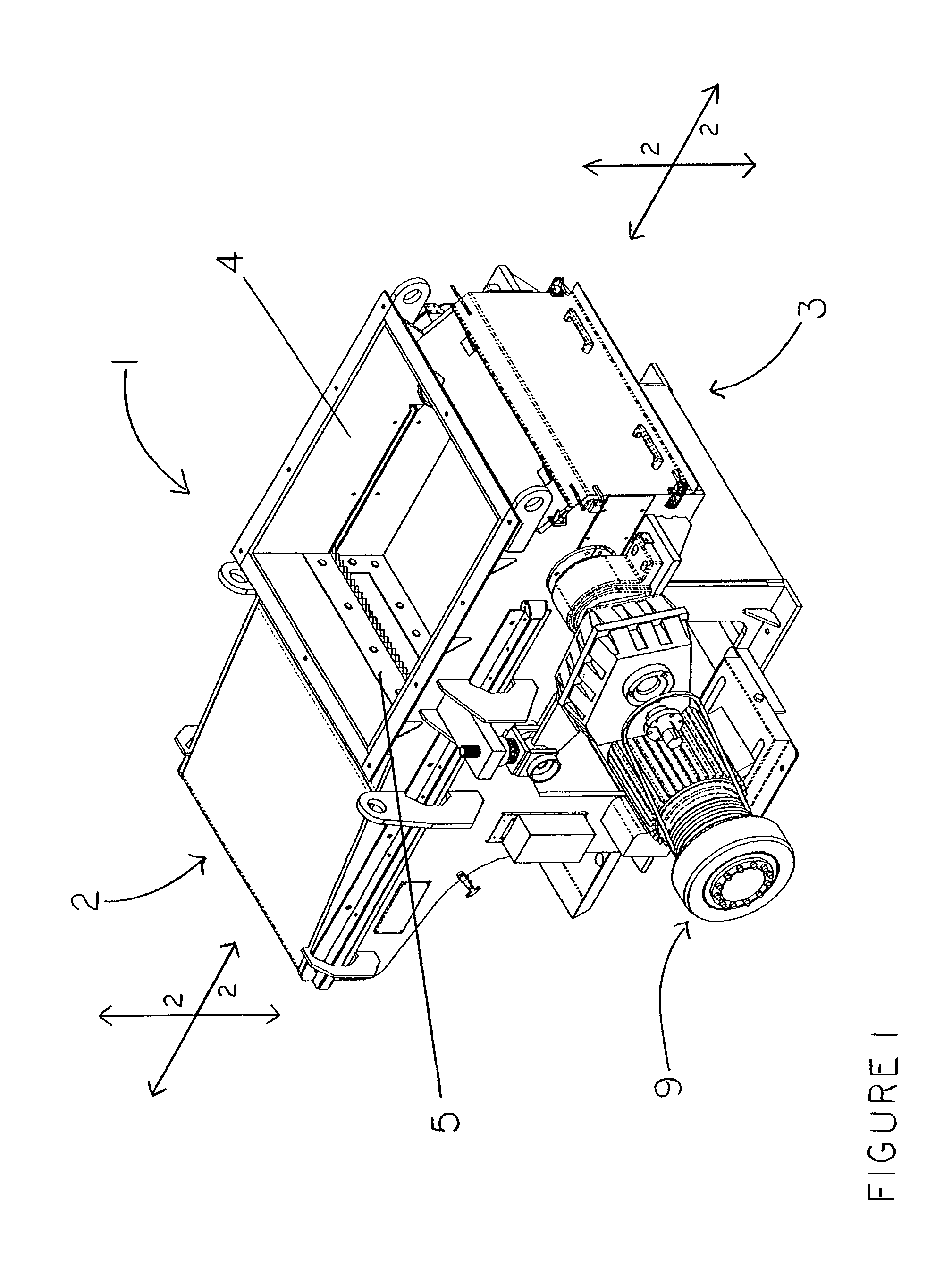
[0036]With reference to the Figures, FIG. 1 shows a prior art rotary grinder 1 having a front end 2, a back end 3, a hopper 4, a ram 5 in retracted position, a rotor 6 (not shown), at least one counter knife 7 (not shown), a plurality of cutters 8 and a motor 9 which provides power to the rotor 6.

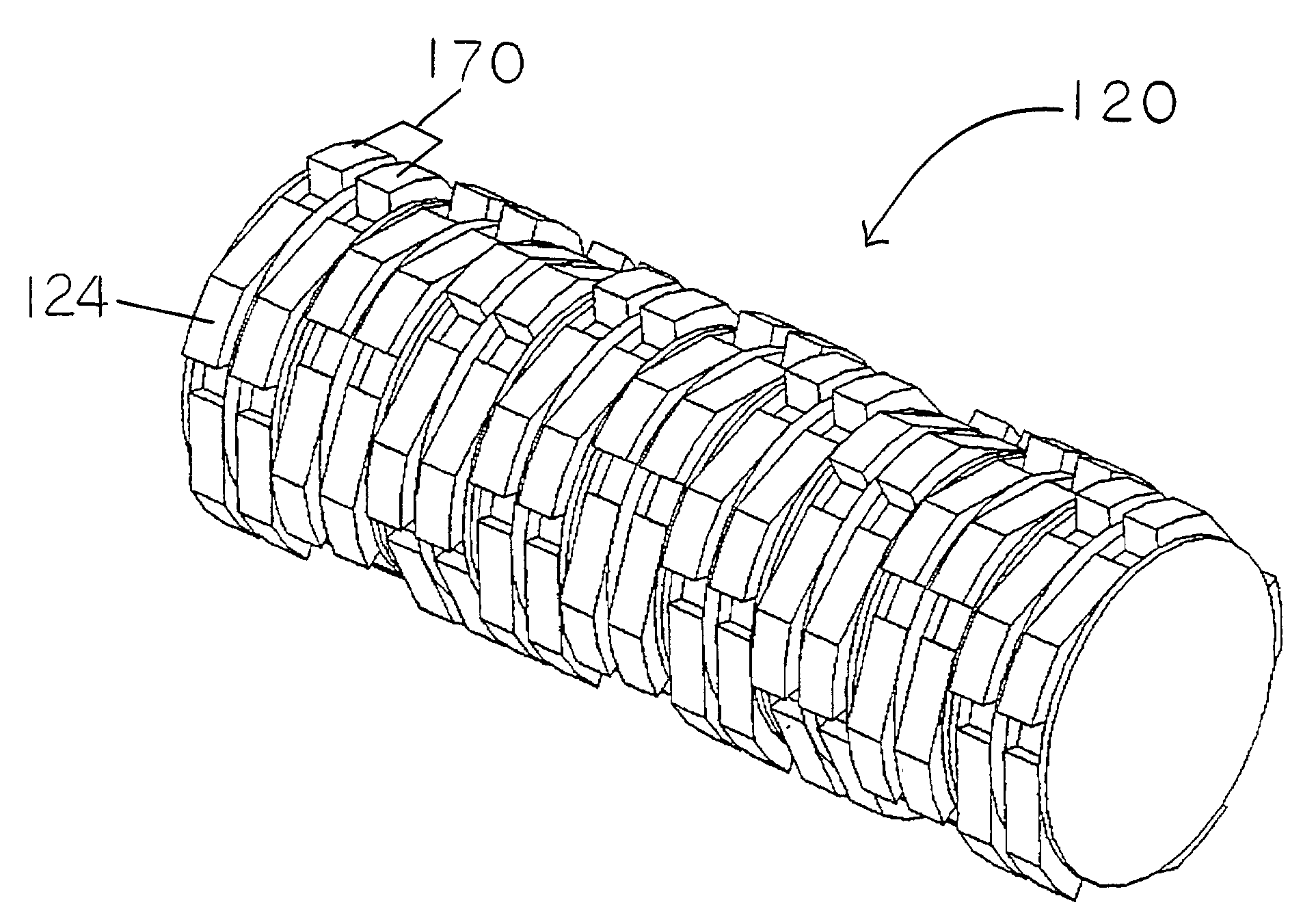
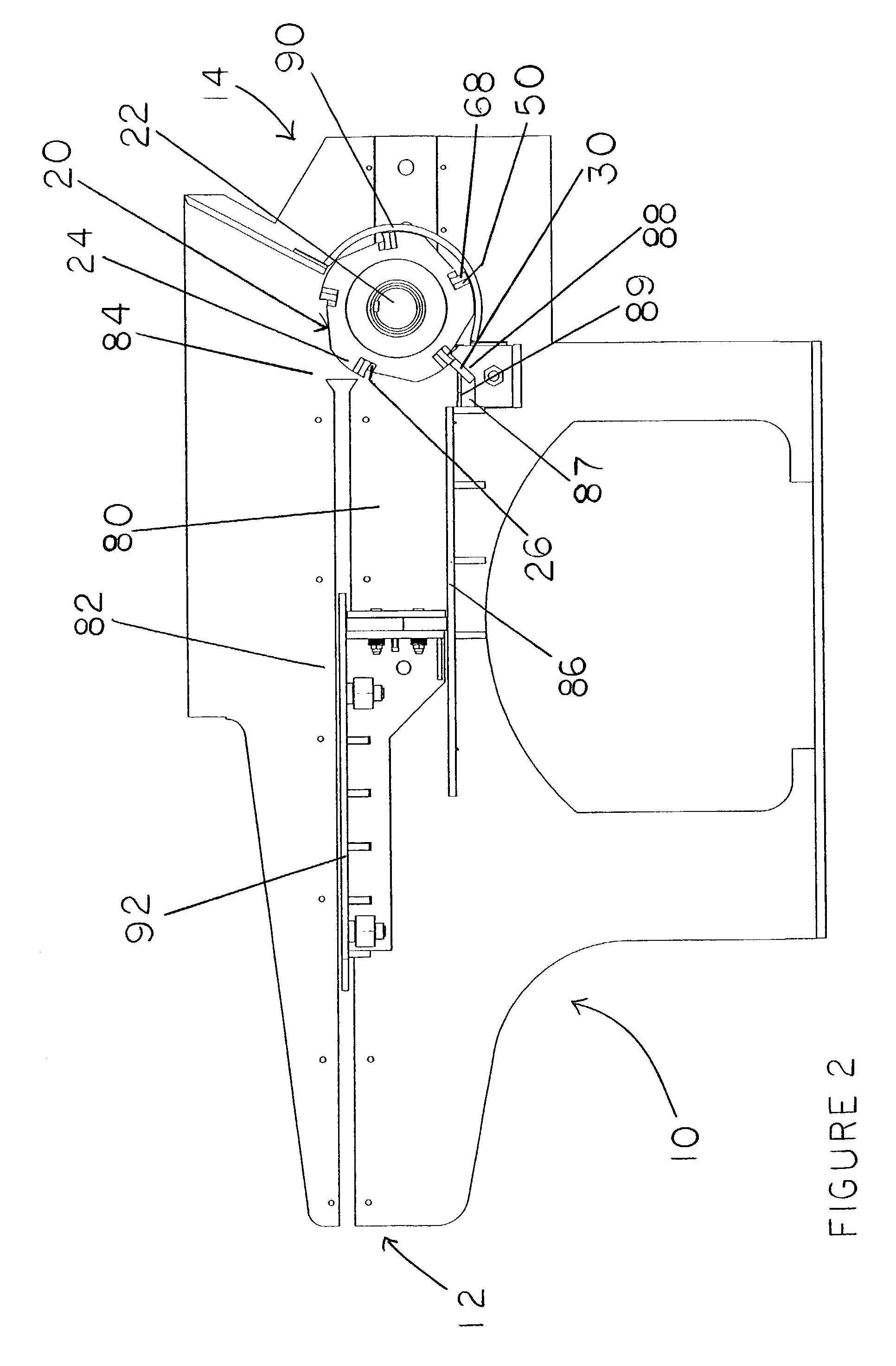
[0037]FIG. 2 shows a rotary grinder 10 similar to the rotary grinder 1 of FIG. 1, but containing an embodiment of the rotor 20 and counter knife 30 combination in the comb configuration of the present invention. The rotary grinder 10 of FIG. 2 has a front end 12; a back end 14; a hopper 80 having a hopper front end 82, a hopper back end 84, a hopper floor 86, and a trough 87 with an angled trough wall 88 in the hopper floor 86 at the hopper back end 84; a ram 92 shown in a partially retracted position towards the hopper front end 82; a rotor 20 mounted on a shaft 22 (see also, FIG. 5) at the hopper back end 84; at least one counter knife 30 mounted on the angled trough wall 88; a filler pla...


PUM

PropertyMeasurementUnit
thicknessaaaaaaaaaa
widthaaaaaaaaaa
widthaaaaaaaaaa

Abstract

The present invention relates to a single shaft rotary grinder with an improved cutter and combination “comb” rotor and counter knife configuration for reducing film, fibrous material and other material which has a tendency to wrap around the rotor, rubber, solid plastics and wood. Reducing this type of material, such as plastic film, into small pieces has been problematic. This invention provides one or more comb shaped counter knives and a rotor having a plurality of geometrically shaped cutters mounted in a plurality of partial or full rows longitudinally along the rotor. The comb shaped counter knives and the rows of cutters work in cooperation to reduce film and other material into small pieces.

Description

CROSS REFERENCE TO RELATED APPLICATION[0001]This application claims the benefit of U.S. Provisional Application No. 60 / 325,621, filed Sep. 28, 2001.BACKGROUND OF THE INVENTION[0002](a) Field of the Invention[0003]The present invention relates to a single shaft rotary grinder with an improved cutter and combination “comb” rotor and counter knife configuration for reducing film, fibrous material and other material which has a tendency to wrap around the rotor, rubber, solid plastics and wood. Reducing this type of material, such as plastic film, into small pieces has been problematic. This invention provides one or more comb shaped counter knives and a rotor having a plurality of geometrically shaped cutters mounted in a plurality of partial or full rows longitudinally along the rotor. The comb shaped counter knives and the rows of cutters work in cooperation to reduce film and other material into small pieces.[0004](b) Description of the Prior Art[0005]U.S. Pat. No. 3,760,673, to Pet...

Claims


Application Information

Patent Timeline
Patent Type & Authority Patents(United States)
IPC IPC(8): B02C1/10B02C13/28B02C15/16B02C17/20B02C23/00B02C7/12B02C18/14B02C18/18
CPCB02C18/145B02C18/148B02C18/18B02C2018/188Y10T83/7809Y10T83/9372
Inventor SOTSKY, GEORGE R.
Owner RAPID GRANULATOR INC
Why Eureka
Try Eureka