Variable speed gearbox with an independently variable speed tail rotor system for a rotary wing aircraft

a technology of variable speed gearbox and tail rotor, which is applied in the direction of mechanical equipment, transportation and packaging, etc., can solve the problems of slow airflow velocity across the retreating blade, the tendency of the retreating blade to stall at high forward airspeed, and the limitation of the forward airspeed of the conventional rotary wing aircraft. achieve the effect of maximizing aircraft performan

Inactive Publication Date: 2008-10-14
SIKORSKY AIRCRAFT CORP
View PDF47 Cites 37 Cited by
  • Summary
  • Abstract
  • Description
  • Claims
  • Application Information

AI Technical Summary

Benefits of technology

[0007]A gearbox of a rotary-wing aircraft according to the present invention receives engine power through a gear train such that the power therefrom is distributed to a main rotor system and a tail rotor system. The gearbox includes at least one variable speed system which optimizes the main rotor speed for different flight regimes such as a hover flight profile and a high speed cruise flight profile. Typically during landing, take-off, hover and low speed flight profiles, a lower main rotor speed is desirable for increased lifting capabilities while in a high speed cruise flight profile a higher main rotor speed is desired for improved rotor performance and higher forward airspeed.
[0010]Another gearbox embodiment locates a variable speed system downstream of the last gear reduction stage and just upstream of the main rotor shaft. This again allows for the variation of main rotor speed while maintaining a constant tail rotor speed with only a single variable speed system which eliminates the synchronization requirement of the above embodiment.
[0011]The present invention therefore provides a main gearbox system for a rotary-wing aircraft to maximize aircraft performance during a hover flight profile and a high speed cruise flight profile, respectively without affecting yaw control.

Problems solved by technology

The forward airspeed of a conventional rotary wing aircraft is limited by a number of factors.
Among these is the tendency of the retreating blade to stall at high forward airspeeds.
As the forward airspeed increases, the airflow velocity across the retreating blade slows such that the blade may approach a stall condition.
This dissymmetry of lift may create an unstable condition if not equalized across the advancing and retreating sectors of the rotor disc.
However, as forward airspeed increases beyond a given point for a given rotor rpm, the flapping and feathering action eventually becomes inadequate to maintain substantial equality of lift over the rotor disc.
This prevents conventional rotary wing aircraft from benefiting from decreased rotor speed because the reduced tail rotor speed unacceptably reduces yaw control, so that the desired main rotor speed is not achievable.
The tail rotor noise reduction is desirable for operation in populated and congested areas, but is often not possible because flight performance factors prevent a reduction in main rotor speed concurrent with the desirable tail rotor speed reduction.

Method used


Image

  • Variable speed gearbox with an independently variable speed tail rotor system for a rotary wing aircraft
  • Variable speed gearbox with an independently variable speed tail rotor system for a rotary wing aircraft
  • Variable speed gearbox with an independently variable speed tail rotor system for a rotary wing aircraft

Examples


Embodiment Construction

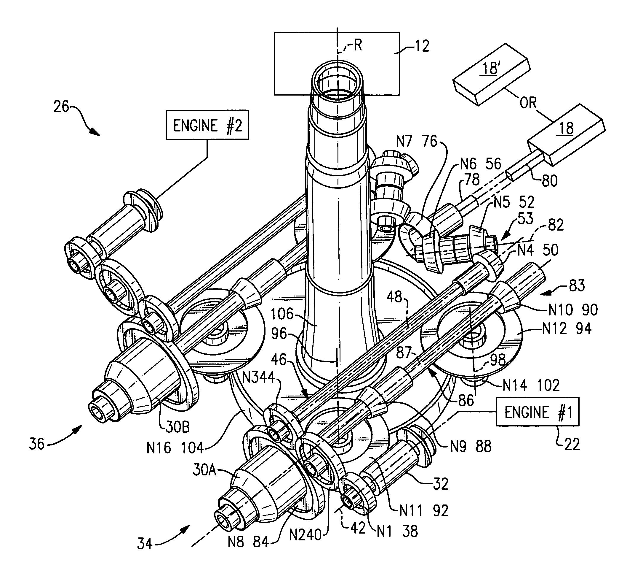
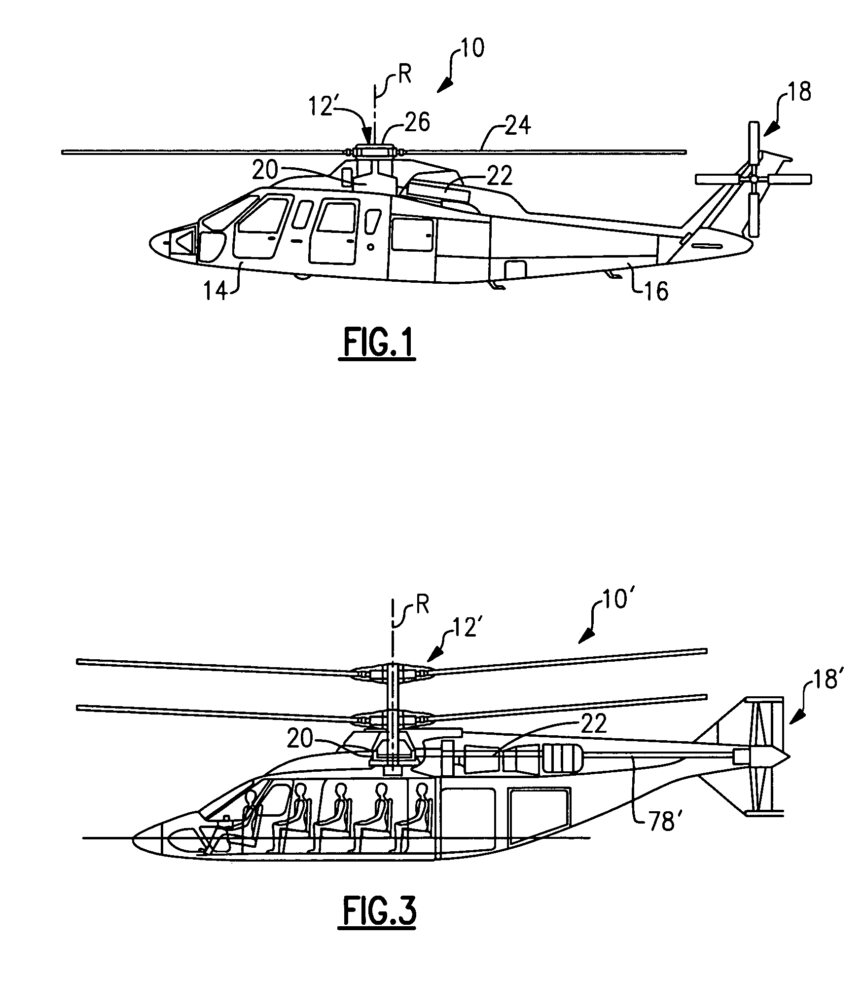
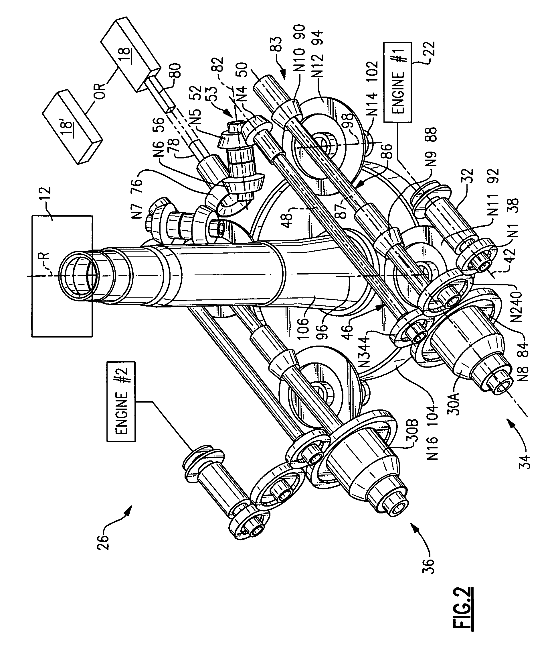
[0017]FIG. 1 schematically illustrates a rotary-wing aircraft 10 having a main rotor system 12. The aircraft 10 includes an airframe 14 having an extending tail 16 which mounts a tail rotor system 18, such as an anti-torque system, a translational thrust system (FIG. 3), a pusher propeller, a rotor propulsion system, and such like. The main rotor assembly 12 is driven about an axis of rotation R through a main gearbox (illustrated schematically at 20) by one or more engines 22. The main rotor system 12 includes a multiple of rotor blades 24 mounted to a rotor hub 26. Although a particular helicopter configuration is illustrated and described in the disclosed embodiment, other configurations and / or machines, such as high speed compound rotary wing aircraft with supplemental translational thrust systems, dual contra-rotating, coaxial rotor system aircraft, turbo-props, tilt-rotors and tilt-wing aircraft, will also benefit from the present invention.

[0018]The main gearbox 20 is prefera...


PUM


Abstract

A gearbox of a rotary-wing aircraft includes at least one variable speed system which optimizes the main rotor speed for different flight regimes such as a hover flight profile and a high speed cruise flight profile for any rotary wing aircraft while maintaining an independently variable tail rotor speed.

Description

BACKGROUND OF THE INVENTION[0001]The present invention relates to a rotary-wing aircraft, and more particularly to a variable speed rotary wing transmission gearbox system that allows operations at different ratios between the main rotor speed while maintaining an independently variable tail rotor speed.[0002]The forward airspeed of a conventional rotary wing aircraft is limited by a number of factors. Among these is the tendency of the retreating blade to stall at high forward airspeeds. As the forward airspeed increases, the airflow velocity across the retreating blade slows such that the blade may approach a stall condition. In contrast, the airflow velocity across the advancing blade increases with increasing forward speed. Dissymmetry of lift is thereby generated as forward air speed increases.[0003]This dissymmetry of lift may create an unstable condition if not equalized across the advancing and retreating sectors of the rotor disc. Typically, blade flapping and feathering ar...

Claims


Application Information

Patent Timeline
Patent Type & Authority Patents(United States)
IPC IPC(8): B64C27/00B64C27/08B64D35/00F16H15/38
CPCB64C27/14B64C27/12B64C2027/8236
Inventor LAPPOS, NICHOLAS D.KAREDES, EDWARDVINAYAK, HARSHGMIRYA, YURIY
Owner SIKORSKY AIRCRAFT CORP
Why Eureka
Try Eureka