Deployable step for motor vehicles

a technology for motor vehicles and steps, applied in the field of motor vehicles, can solve the problems of difficulty in reaching the top of the vehicle to remove stored cargo or other, height that may be difficult for the average person to get, and not without their downfalls

Active Publication Date: 2008-10-14
FORD GLOBAL TECH LLC
View PDF15 Cites 40 Cited by
  • Summary
  • Abstract
  • Description
  • Claims
  • Application Information

AI Technical Summary

Benefits of technology

[0009]The above configuration allows for the step of the present invention to be at an optimal height off the ground when fully deployed in the second position, and also allows for the use of a trailer hitch on a motor vehicle independent of the position of the step.

Problems solved by technology

The height of these vehicles, combined with the use of the rooftops for a variety of purposes, is such that the average person cannot reach the top of the vehicle to remove the stored cargo or for other purposes, such as washing the vehicle, without stepping on either the bumper of the vehicle, which is at a height that may be difficult for the average person to get to, or a step stool of some sort.
Devices aiming to satisfy this need have been developed, however, they are not without their downfalls.
However, there are numerous disadvantages associated with this device and others currently in use.
For one, the apparatus does not allow the trailer hitch to be used independent of the step.
Second, the mounting of the step on the hitch apparatus itself results in a less than optimal step height from the ground.
The step height in relation to the ground in this arrangement is slightly lower than that of the bumper, which, therefore, does not provide for the maximum height benefit.
Third, when the apparatus is in its first, or “up”, stowed, position, the apparatus is not flush with the contours of the bumper, resulting in less than desirable aesthetics and less than optimized packaging.

Method used


Image

  • Deployable step for motor vehicles
  • Deployable step for motor vehicles
  • Deployable step for motor vehicles

Examples


Embodiment Construction

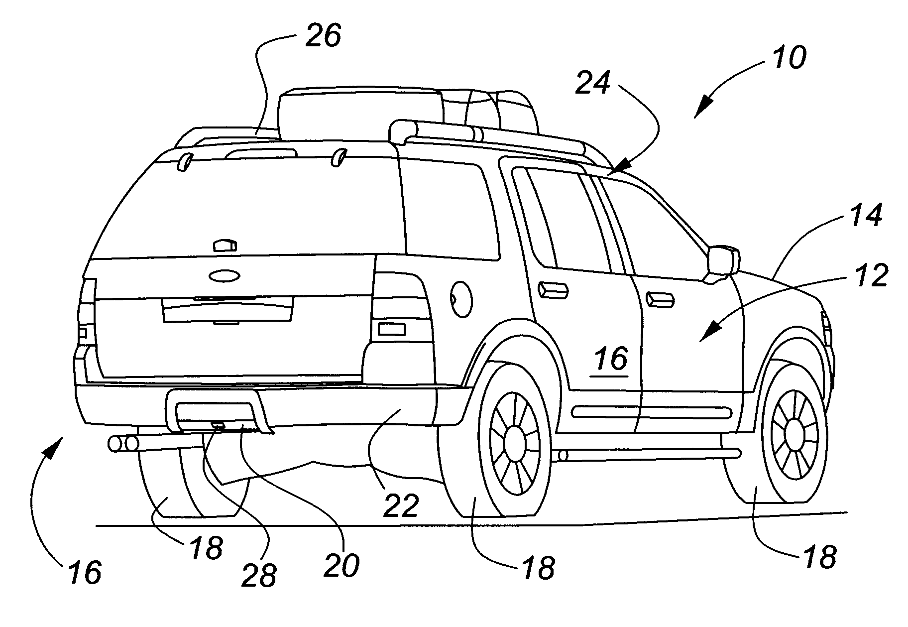
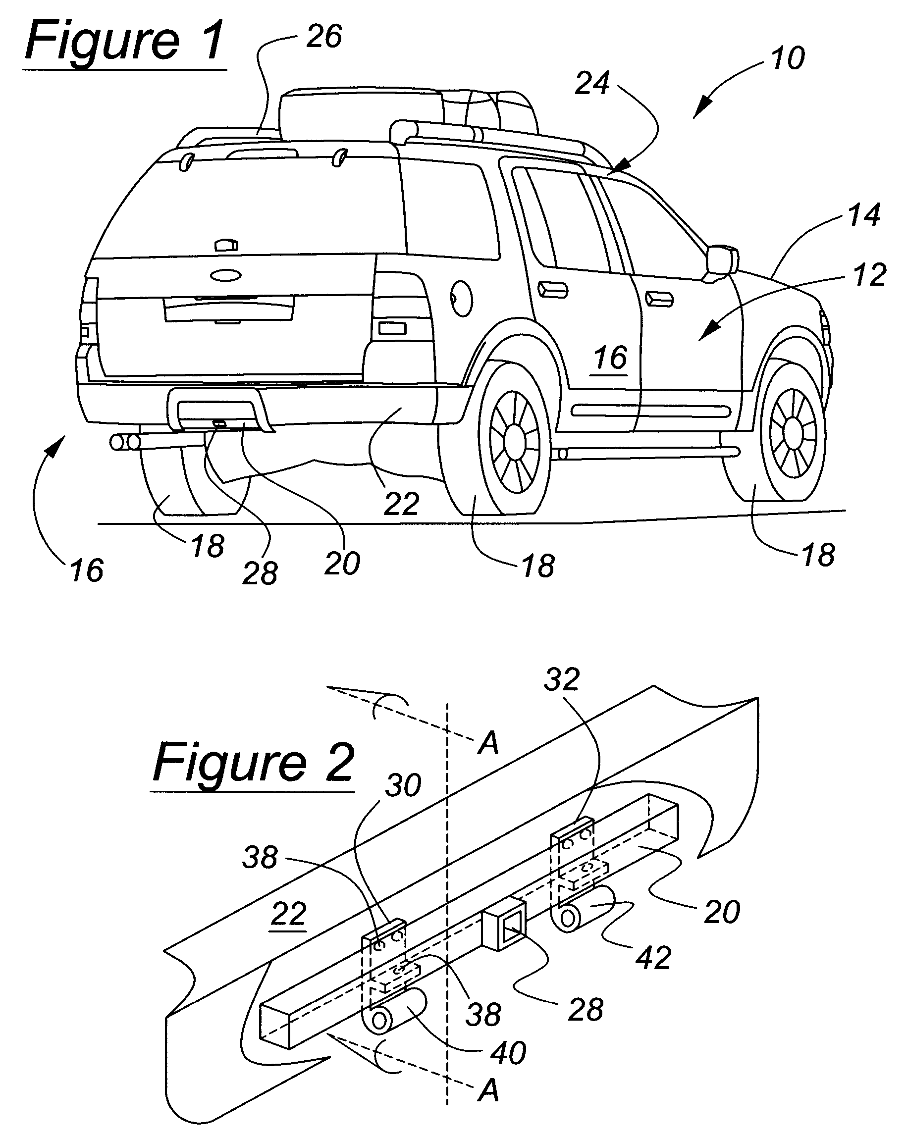
[0021]Referring now to the drawings wherein like reference numerals are used to identify identical components in the various views, FIG. 1 is a perspective view of a motor vehicle 10 in accordance with the present invention. Motor vehicle 10 may take many forms such as a sport utility vehicle (as shown in FIG. 1), a van, or a truck. It should be noted, however, that these are exemplary only, and not meant to be limiting in nature.

[0022]With continued reference to FIG. 1, motor vehicle 10 includes a body 12 having a front end 14 and rear end 16, and further includes a plurality of wheels 18 coupled to body 12; a rear structural member 20; and a rear bumper 22 covering most of structural member 20. Body 12 includes a roof 24 of vehicle 10, and may include a storage device 26 located on roof 24.

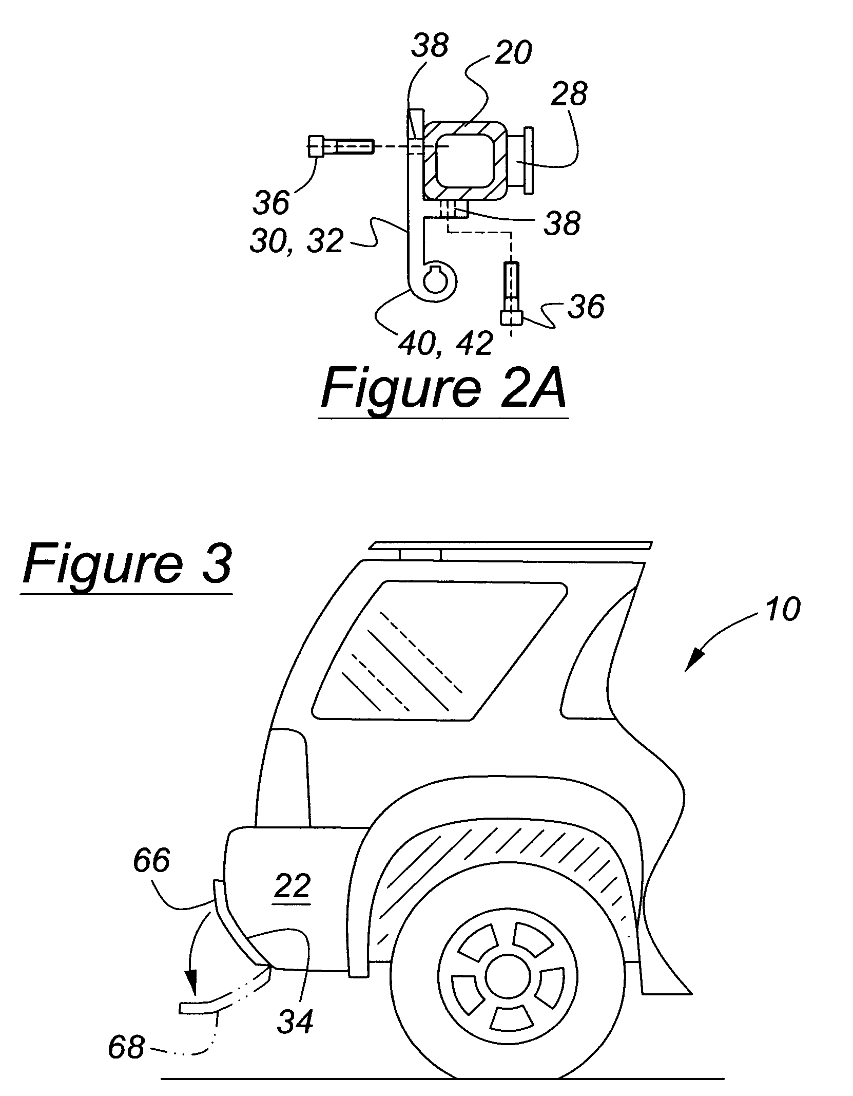
[0023]FIG. 2 is a partial perspective view of the rear of the vehicle, wherein the relationship between various components of the present invention are illustrated. Structural member 20 may be a...


PUM


Abstract

A motor vehicle in accordance with the present invention includes a body having a front end, a rear end, a roof, and a rear structural member located at the rear end of the body. A motor vehicle further includes a plurality of wheels coupled to the body. A pair of brackets is coupled to the rear structural member. A rear bumper is configured to both cover the structural member and to allow for access to the brackets. A step is pivotally coupled to the brackets, and therefore to the structural member and motor vehicle. The step is operative to articulate about an axis between a first and second position.

Description

BACKGROUND OF INVENTION[0001]1. Technical Field of Invention[0002]The present invention generally relates to motor vehicles. In particular, the present invention relates to a deployable step for motor vehicles.[0003]2. Background of Invention[0004]Trucks and sport utility vehicles have become commonplace as a means for everyday transportation on roads around the world, as well as for both on-road and off-road recreational uses. These vehicles tend to be tall in comparison to typical passenger automobiles, and often include accessories on the roof of the vehicle such as luggage racks, bike racks, and other similar storage devices. Additionally, these vehicles are almost universally equipped with a trailer hitch that can be used for, among other things, towing campers, boats, and trailers.[0005]The height of these vehicles, combined with the use of the rooftops for a variety of purposes, is such that the average person cannot reach the top of the vehicle to remove the stored cargo or ...

Claims


Application Information

Patent Timeline
Patent Type & Authority Patents(United States)
IPC IPC(8): B60D1/60B62C3/00B60R3/02
CPCB60R3/02
Inventor WILLIAMS, BRUCE PRESTON
Owner FORD GLOBAL TECH LLC
Why Eureka
Try Eureka