
Combination ergonomic chair and seat pivoting mechanism

Inactive Publication Date: 2008-10-14
HODGES GEORGE A
View PDF13 Cites 24 Cited by
  • Summary
  • Abstract
  • Description
  • Claims
  • Application Information

AI Technical Summary

Benefits of technology

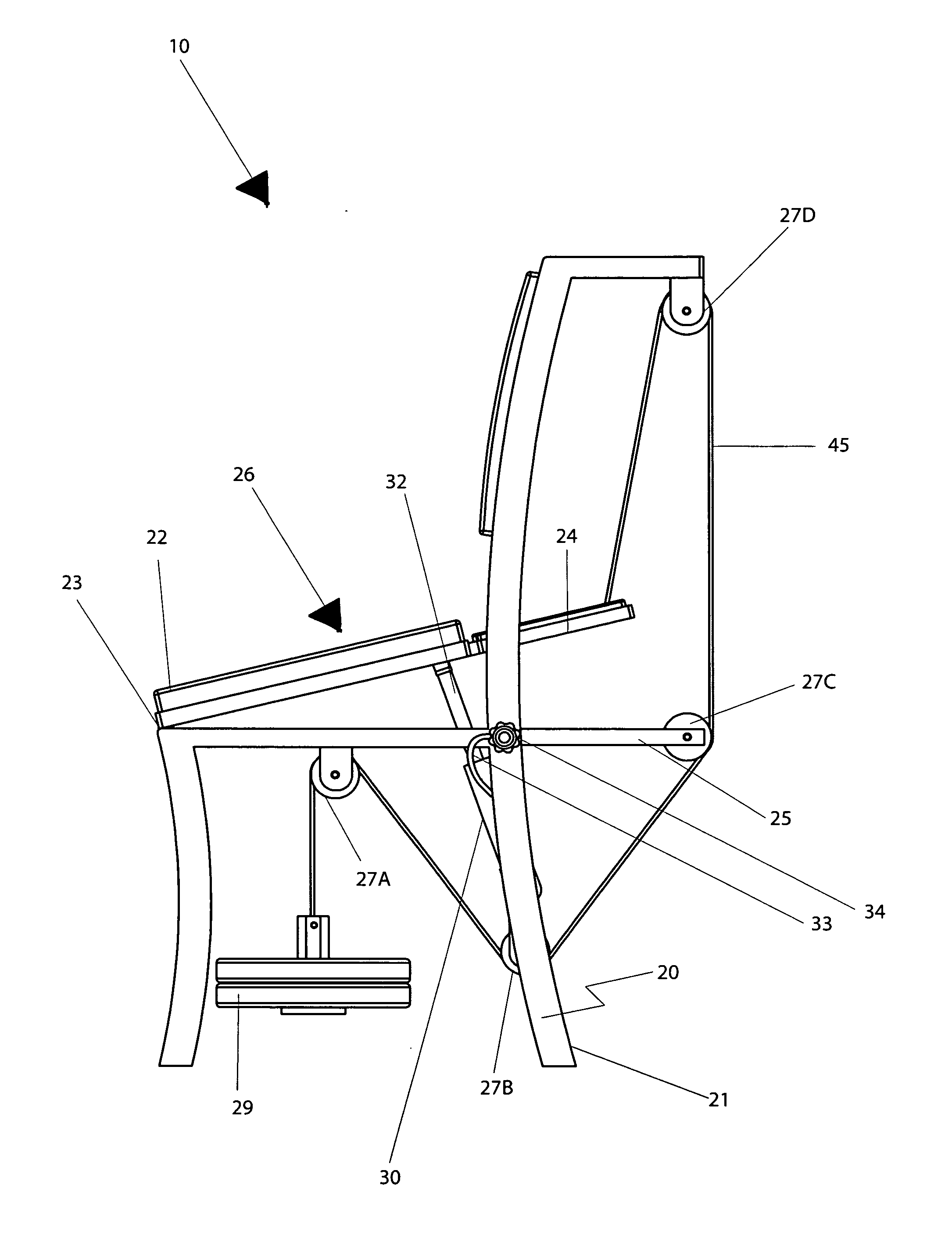
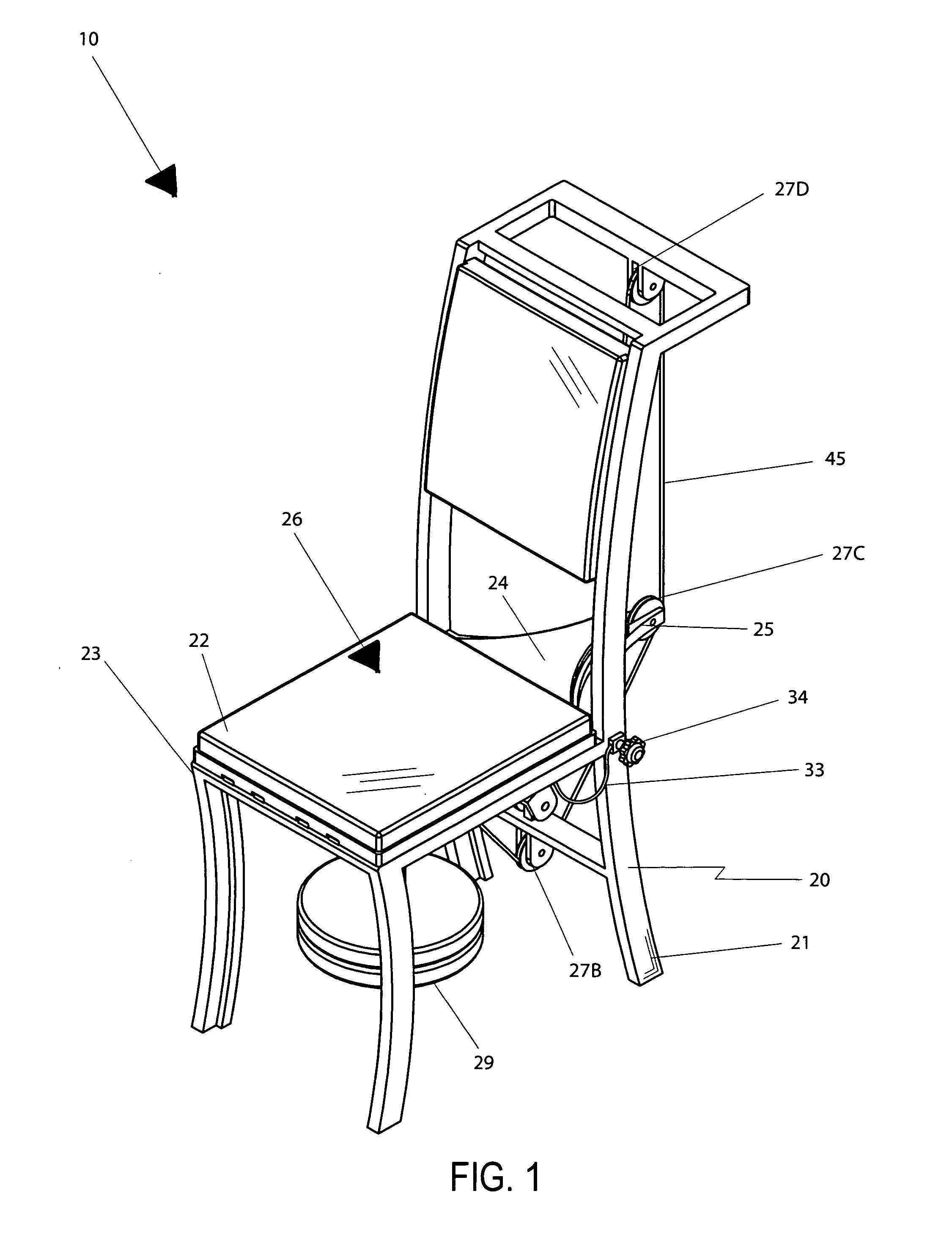
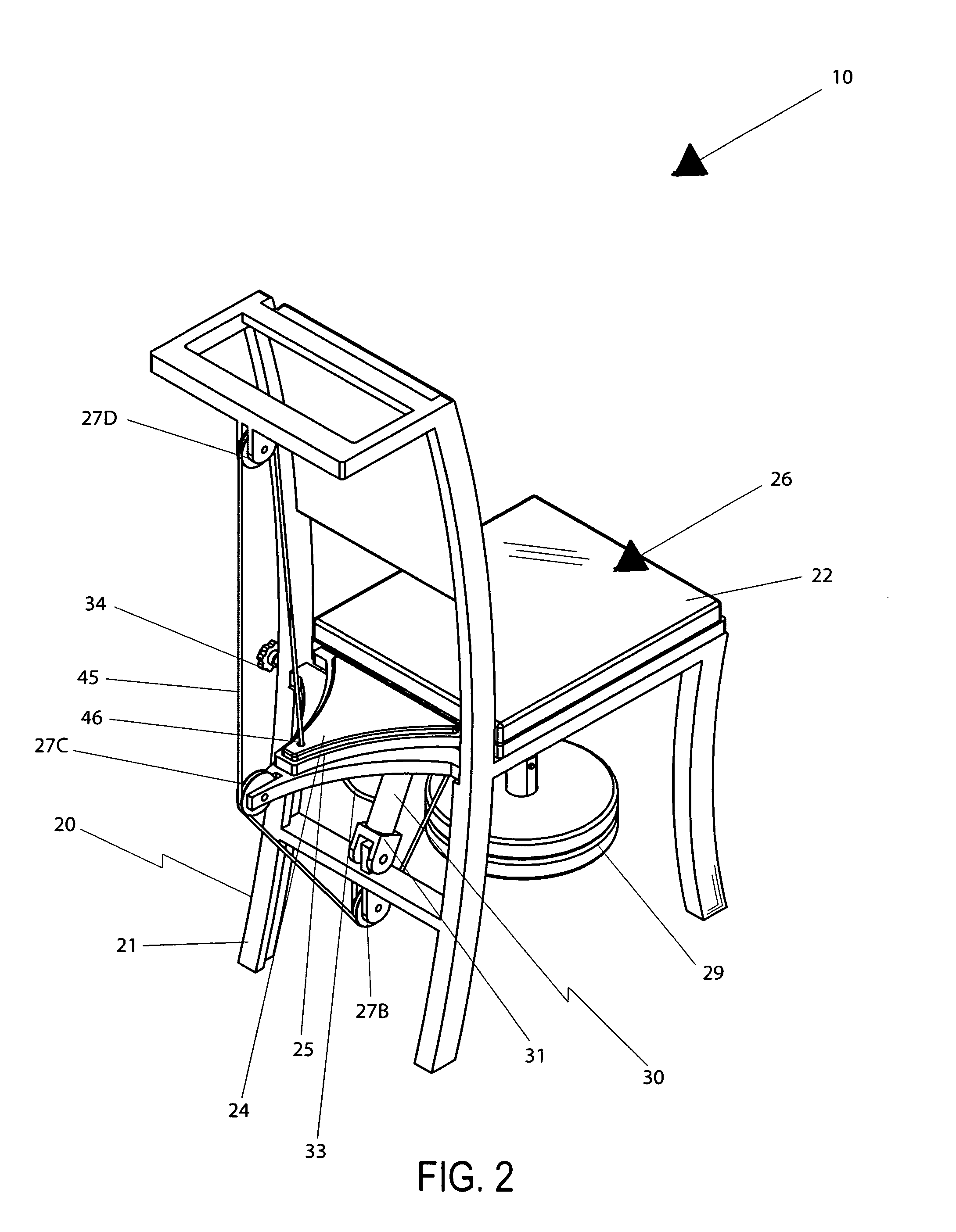
[0016]The assembly further includes a pneumatic piston that has a stationary portion directly coupled to the frame, and further has a linear piston directly coupled to the seat section. Such a stationary portion and linear piston of the pneumatic piston are pivotally coupled to the frame and the seat section respectively. The pneumatic piston and weight member conveniently cooperate in tandem for effectively resisting an operating force directed on the seat section during sitting and standing procedures such that the user weight is gradually transferred between equilibrium and non-equilibrium positions respectively. Such a pneumatic piston includes a flexible conduit and a rotatable valve that has an outlet port in fluid communication with the flexible conduit. Such a flexible conduit is directly coupled to the pneumatic piston such that the pneumatic piston is effectively restricted from telescopically retracting to a fully compressed position based upon a rotational movement of the valve.

Problems solved by technology

Persons recovering from surgery, suffering from arthritis, or otherwise partially incapacitated are often incapable of lifting themselves from a sitting position without the assistance of another person.
Persons with muscle weakness or other conditions also find it difficult to lower themselves carefully and safely to a sitting position.
Unfortunately, this prior art example does not provide a counter weight to assist a user in raising or lowering a user body weight during operating conditions.
Unfortunately, this prior art example requires a power source to utilize the chair, which may not be available, thus rendering the invention useless for its intended purpose.
In addition, the large size of this chair impedes its use at kitchen tables or desks, as examples.

Method used


Image

  • Combination ergonomic chair and seat pivoting mechanism
  • Combination ergonomic chair and seat pivoting mechanism
  • Combination ergonomic chair and seat pivoting mechanism

Examples


Embodiment Construction

[0029]The present invention will now be described more fully hereinafter with reference to the accompanying drawings, in which a preferred embodiment of the invention is shown. This invention may, however, be embodied in many different forms and should not be construed as limited to the embodiment set forth herein. Rather, this embodiment is provided so that this application will be thorough and complete, and will fully convey the true scope of the invention to those skilled in the art. Like numbers refer to like elements throughout the figures.

[0030]The assembly of this invention is referred to generally in FIGS. 1-9 by the reference numeral 10 and is intended to provide a combination ergonomic chair and seat pivoting mechanism. It should be understood that the assembly 10 may be used to assist many different types of users and should not be limited in use to assisting only those types of users described herein.

[0031]Referring initially to FIGS. 1, 2, 3, 4, 5, 6, 7, 8 and 9, the as...


PUM


Abstract

A combination chair and seat pivoting mechanism includes a frame and a seat section pivotally connected to a front end of the frame. The seat section is pivotal along a fulcrum axis defined along a front end thereof. The front end remains contiguously abutted with the frame during pivoting motions. Pulleys are connected to spaced portions of the frame and are registered along a single plane. A weight member is coupled to the pulleys and positioned subjacent to the seat section. A cable is tethered to the frame and the weight member. A pneumatic piston has a stationary portion coupled to the frame, and a linear piston coupled to the seat section. The pneumatic piston and weight member cooperate in tandem for resisting an operating force directed on the seat section during sitting and standing procedures.

Description

CROSS REFERENCE TO RELATED APPLICATIONS[0001]This application claims the benefit of U.S. Provisional Application No. 60 / 739,770, filed Nov. 28, 2005.STATEMENT REGARDING FEDERALLY SPONSORED RESEARCH OR DEVELOPMENT[0002]Not Applicable.REFERENCE TO A MICROFICHE APPENDIX[0003]Not Applicable.BACKGROUND OF THE INVENTION[0004]1. Technical Field[0005]This invention relates to chairs and, more particularly, to a combination ergonomic chair and seat pivoting mechanism for assisting a user to transfer their body mass between sitting and standing positions.[0006]2. Prior Art[0007]Persons recovering from surgery, suffering from arthritis, or otherwise partially incapacitated are often incapable of lifting themselves from a sitting position without the assistance of another person. Persons with muscle weakness or other conditions also find it difficult to lower themselves carefully and safely to a sitting position. One of the solutions proposed for enabling these persons to rise out of a chair wi...

Claims


Application Information

Patent Timeline
IPC IPC(8): A47C1/00
CPCA61G5/14Y10S297/10
Inventor HODGES, GEORGE A.
Owner HODGES GEORGE A
Learn More