Microwave discharge apparatus

Inactive Publication Date: 2003-05-13
TAKAMATSU TOSHIYUKI
View PDF13 Cites 12 Cited by
  • Summary
  • Abstract
  • Description
  • Claims
  • Application Information

AI Technical Summary

Problems solved by technology

Consequently, the structure is not practically useful.
Further, the dielectric-tube cannot include many electric peaks of the microwave due to the structure itself.
The structure suffers much loss in the thermal conversion.
The structure costs much because of the attachment.
Therefore, it is difficult to have whole microwave absorbed in such structures without passing through both sides of the dielectric tube.
The design of the apparatus is severely restricted due to the reason.
That results in not only the restriction in designing an apparatus but also lowering of efficiency as each functional parts are connected in the solid circuit, and the electric transmission has a loss.
Therefore, the structure als

Method used


Image

  • Microwave discharge apparatus
  • Microwave discharge apparatus
  • Microwave discharge apparatus

Examples


Embodiment Construction

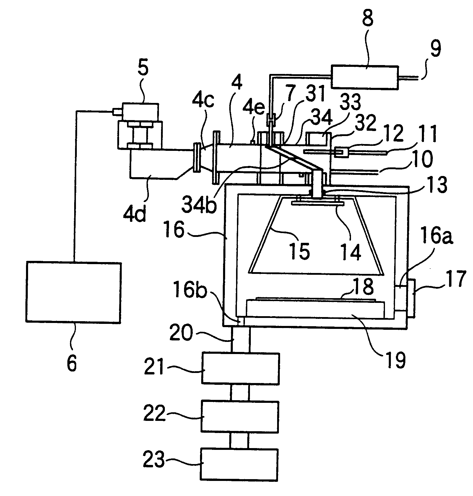
This invention will be described in the further detail with reference to the accompanying drawings.

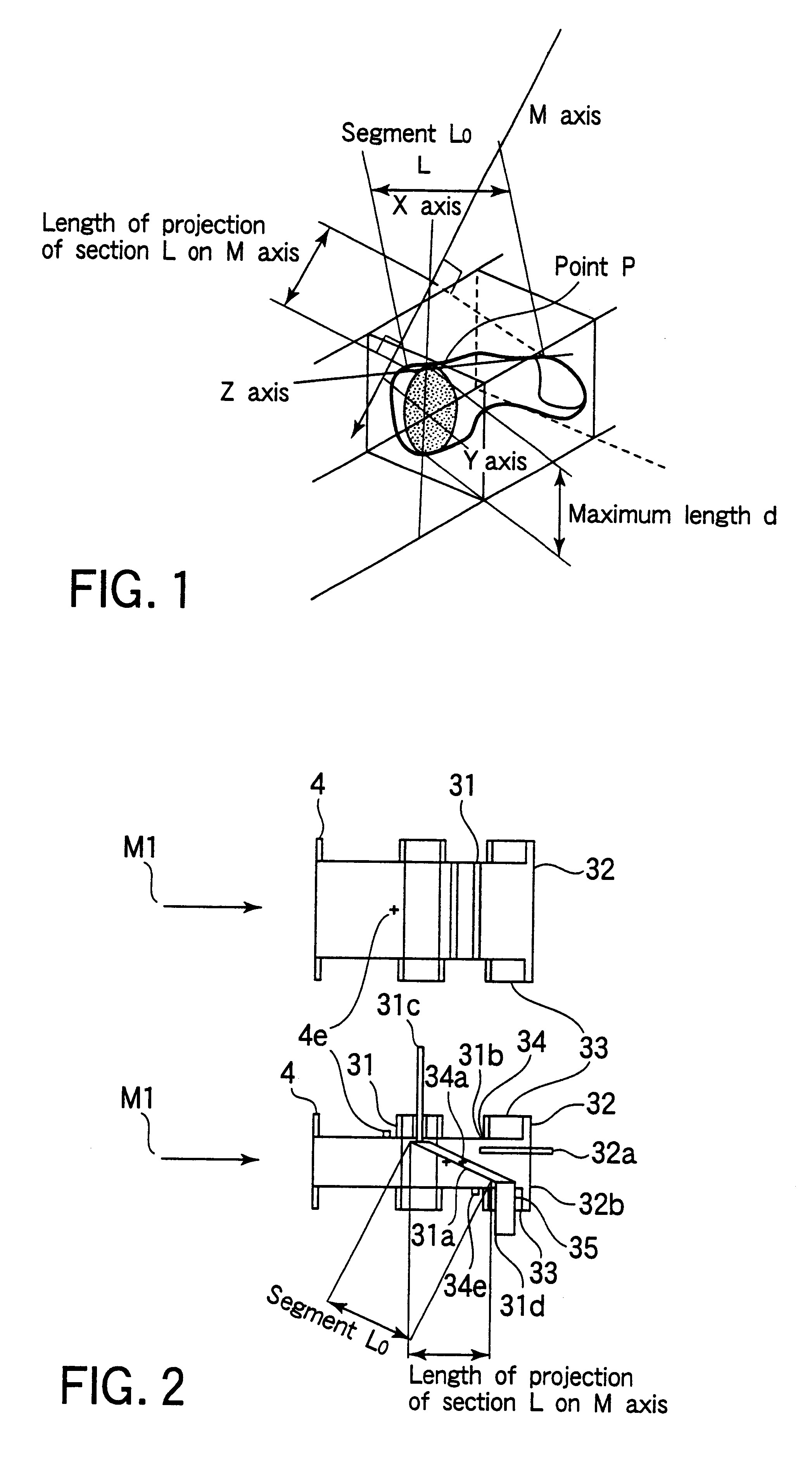
FIG. 1 specifies the general structure of the discharge tube of this invention. The tube is made of dielectric material. M axis represents the direction in which a microwave travels.

The surface of the metallic member has a similar shape to the facing surface of the discharge tube. The tube is located close to the dielectric tube on the opposite side to the direction in which a microwave travels and cooled.

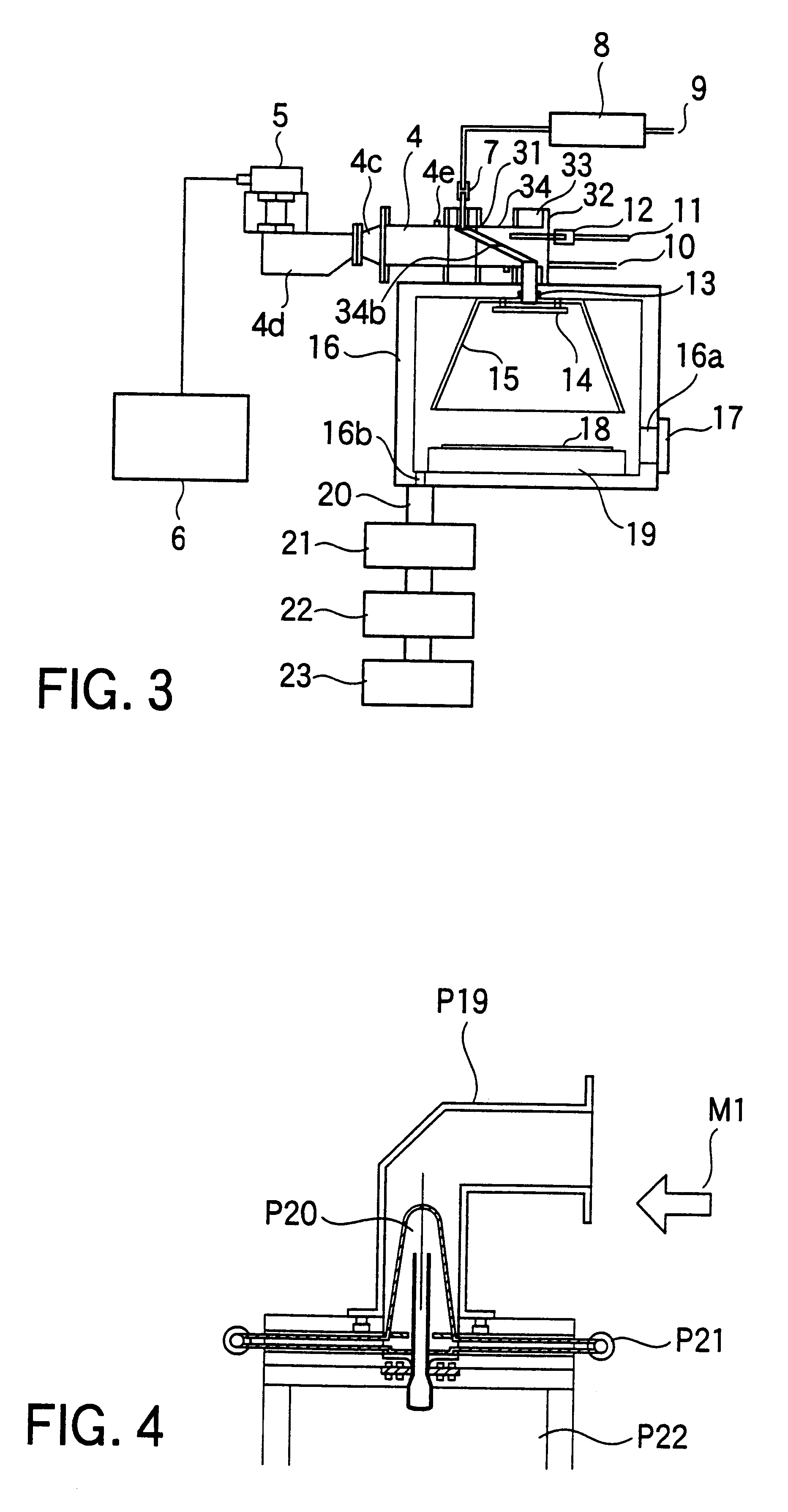
Thus, the phase of a microwave converges and many peaks of it are generated between the inclined surface of the metallic member and the waveguide walls or the walls of the metallic flame connected with the waveguide. Consequently, the plasma discharge is easily caused in the dielectric tube located close to the metal surface on the microwave oscillator side from the beginning of microwave oscillation till the beginning of the electric discharge. The plasma in the dielectric tube absor...


PUM

PropertyMeasurementUnit
Temperatureaaaaaaaaaa
Flow rateaaaaaaaaaa
Densityaaaaaaaaaa

Abstract

A discharge tube (31) provided inside the cavity of a waveguide (4) is so structured as to monotonously decrease the cross section of the cavity in the direction in which the microwave travels and thereby to close the cavity. The waveguide (34) has vent holes (34a, 34c) made through the tube wall. A metallic member (32) monotonously decreasing the cross section of the cavity in the direction in which the microwave travels and thereby closing the cavity is provided on the opposite side to the discharge tube (31) in the direction in which the microwave travels. A fluid is made to flow through the metallic member. A gas introducing port is provided in the discharge tube (31), and a gas exhaust port is provided also in the discharge tube (31) on the opposite side to the gas introducing port with respect to the center axis of the waveguide (34). Thus, no standing wave is generated from the time when a plasma is created, the plasma absorbs energy at high efficiency, the temperature at the wall of the discharge area little increases, and the density of active particles is high.

Description

This application is a U.S. National Phase Application under 35 USC 371 of International Application PCT / JP99 / 03650 (not published in English) filed Jul. 6, 1999.1. Technical FieldThis invention relates to a microwave discharge apparatus for creating and keeping a plasma with efficiently absorbing microwave and not generating much reflected wave, and efficiently cooling the discharge vessel made of dielectric substance.2. Background ArtSurface treatments such as etching, Plasma Chemical Vapor Deposition (PCVD) and heat treatment, has already been applied to various industrial fields. Particularly, Plasma Downstream Treatment with setting a sample in the down stream of plasma causes little damage on the sample and is expected for various applications and developments mainly in the field of semiconductor in the future.The most important role of plasma in Plasma Down Stream Treatment is to efficiently generate active particles for use in the process. A microwave on 2.45 GHz band is ofte...

Claims


Application Information

Patent Timeline
IPC IPC(8): C23C16/50H01L21/302H01L21/02H05H1/46
CPCC23C16/511H05H1/46H05H2001/4622H05H1/4622
Inventor TAKAMATSU, TOSHIYUKI
Owner TAKAMATSU TOSHIYUKI
Why Eureka
Try Eureka