Resilient joint for deployable structures

a monolithic joint and deployable technology, applied in the direction of wing accessories, couplings, rod connections, etc., can solve the problems of cumulative clearance between each pair of joint parts, significant problems such as dead bands, dead bands, etc., to limit the flexure's bend radius, less structural efficiency, and constrain the amount of rotation

Active Publication Date: 2008-10-14
THE UNITED STATES OF AMERICA AS REPRESETNED BY THE SEC OF THE AIR FORCE
View PDF15 Cites 34 Cited by
  • Summary
  • Abstract
  • Description
  • Claims
  • Application Information

AI Technical Summary

Benefits of technology

[0009]The combination of these two design elements prevents the strain in the flexure from exceeding its design limit when the joint is at its maximum angular deflection and the attached member is fully collapsed. The joint of the present invention displays strength-stability and stiffness properties comparable to those of a kinematically equivalent, sliding contact mechanism, but without the “dead band” problem.

Problems solved by technology

The inherent problem is that, for a deployable structure using a plurality of such joints, clearance between each pair of joint parts is cumulative.
This creates the problem known as “dead band,” where movement at one end of a structure is not communicated to the other end until the intervening clearances are taken up.
Where structural tolerances are small, “dead band” is a significant problem.
For terrestrial applications, the foregoing may be considered as inconveniences; however, where the deployment is to be extraterrestrial, both of the foregoing present serious drawbacks.
However, both such joints fail to ensure that the maximum design strain of the joint material is not exceeded when the attached member is rotated to an extreme position.
This shortcoming could cause the joint to fail.

Method used


Image

  • Resilient joint for deployable structures
  • Resilient joint for deployable structures
  • Resilient joint for deployable structures

Examples


Embodiment Construction

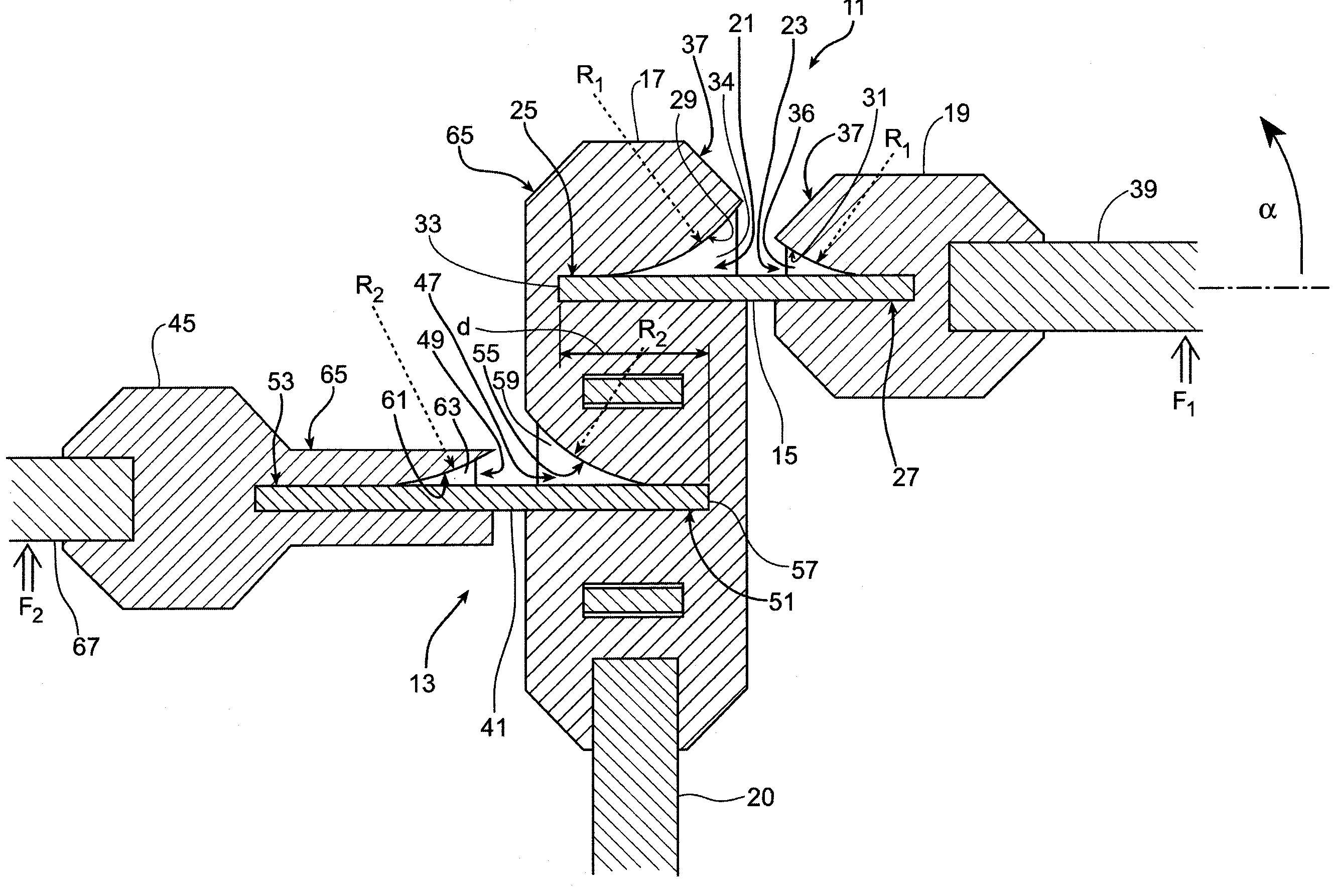
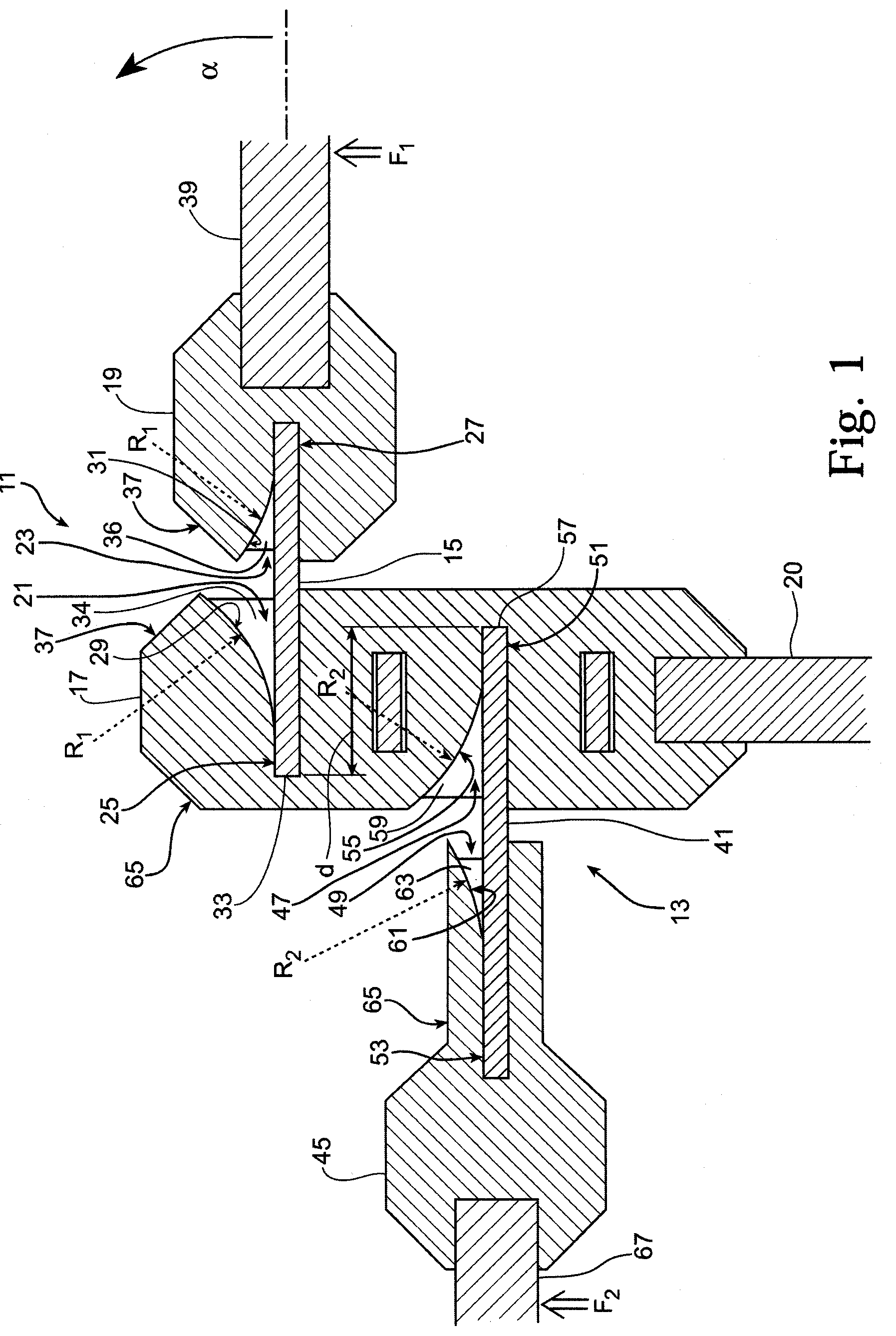
[0017]Turning to the drawings, FIG. 1 illustrates flexure joints 11 and 13 of the present invention. Joint 11 is comprised of flexure 15, structural node 17, and structural connector 19. Node 17 is attached atop nonarticulating rigid member 20. Node 17 includes cavity 21 and connector 19 includes cavity 23. Flexure 15 is attached at its two ends, respectively, to base region 25 of cavity 21 and base region 27 of cavity 23. Cavity 21 includes curved surface 29 having radius of curvature R1. Cavity 23 includes curved surface 31 also having radius of curvature R1. Cavity 21 also includes base 33 and planar, parallel lateral sides, with only side 34 being shown. Cavity 23 also includes planar, parallel lateral sides, with only side 36 being shown. Node 17 and connector 19 include mating surfaces 37. Member 39 is fixedly attached to connector 19.

[0018]Joint 13 is comprised of flexure 41, node 17, and connector 45. Node 17 also includes cavity 47, and connector 45 includes cavity 49. Flex...


PUM


Abstract

A resilient flexure has one end attached within a cavity in a rigid member, and the other end attached within a cavity in a structural mode. The cavities are shaped to limit the flexure's bend radius. The member and the node have mating surfaces that abut to constrain the amount of rotation of the member. The aforementioned elements are shaped to prevent the strain in the flexure from exceeding its design limit when the joint is at its maximum angular deflection and the attached member is fully collapsed.

Description

STATEMENT OF GOVERNMENT INTEREST[0001]The invention described herein may be manufactured and used by or for the Government of the United States for all governmental purposes without the payment of any royalty.BACKGROUND OF THE INVENTION[0002]The present invention is related to a resilient monolithic joint for collapsing a structure to a reduced volume for storage, and subsequently restoring the structure to its useful configuration without requiring the application of an external force. More particularly, the present invention is a joint comprised of a piece of resilient, deformable material attached at one end to a rigid member and at its other end to a structural node. The material can be deformed when it is desired to collapse the member and, when it is desired to deploy the member, will return to its original shape in the absence of the application of an external force.[0003]It is ofttimes necessary to transport a structure that occupies considerable volume. Where space on the v...

Claims


Application Information

Patent Timeline
Patent Type & Authority Patents(United States)
IPC IPC(8): E05D1/00
CPCB64G1/222E05D1/04E05Y2900/502Y10T403/32557Y10T403/45Y10T403/54Y10T403/32098Y10T16/5253Y10T16/525Y10T403/32614
Inventor MURPHEY, THOMAS W.POLLARD, ERIC L.
Owner THE UNITED STATES OF AMERICA AS REPRESETNED BY THE SEC OF THE AIR FORCE
Why Eureka
Try Eureka