

Annular corrugated coaxial cable connector with polymeric spring finger nut
a technology of polymeric spring finger nut and coaxial cable, which is applied in the manufacture of insulating conductor/cable, cable/conductor, cable/device connection, etc., can solve the problems of incompatibility of annular corrugated coaxial cable with annular corrugated solid outer conductor coaxial cable, high manufacturing cost and time-consuming installation
- Summary
- Abstract
- Description
- Claims
- Application Information
AI Technical Summary
Benefits of technology
Problems solved by technology
Method used
Image

Examples
Embodiment Construction
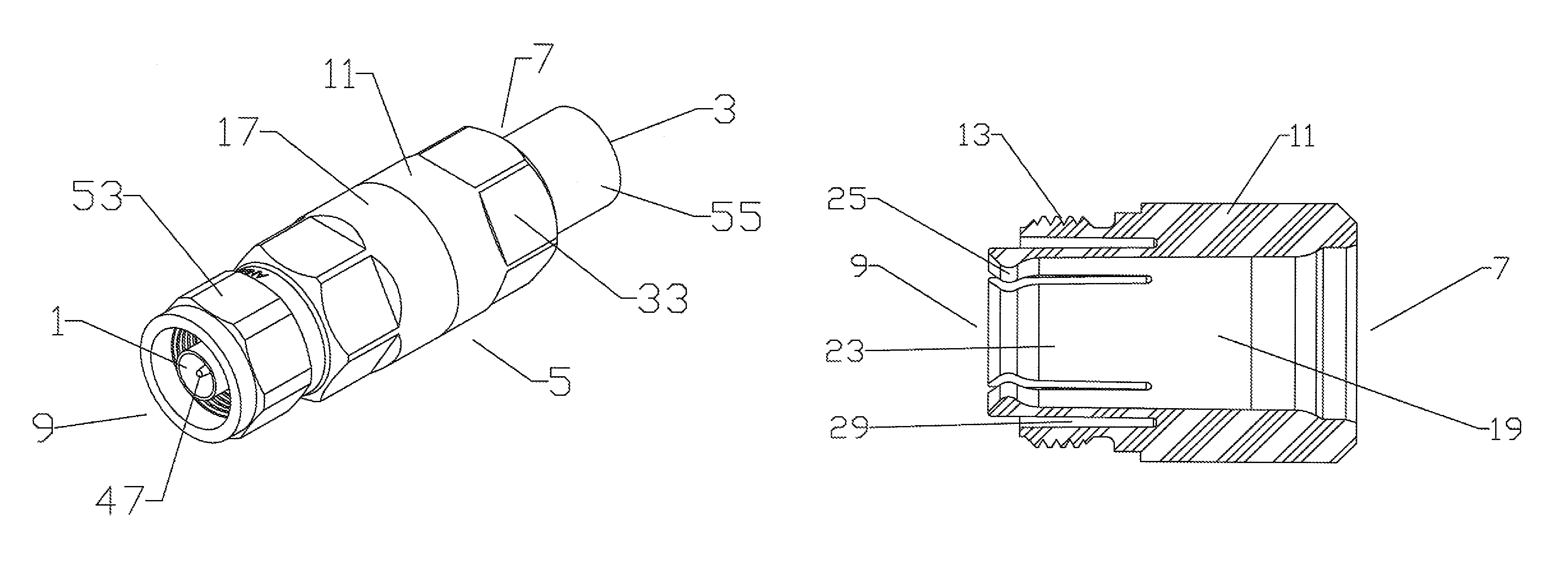
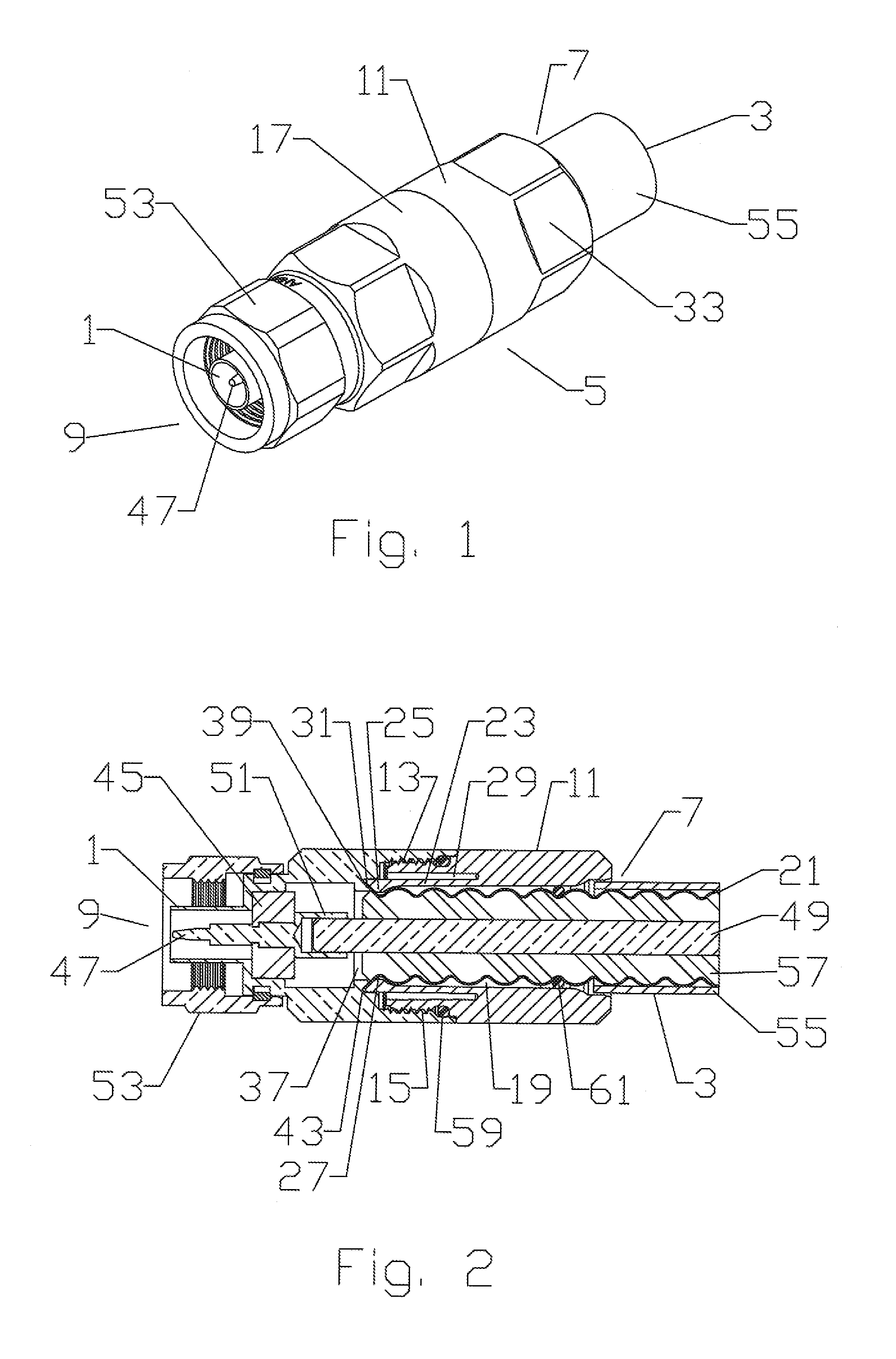
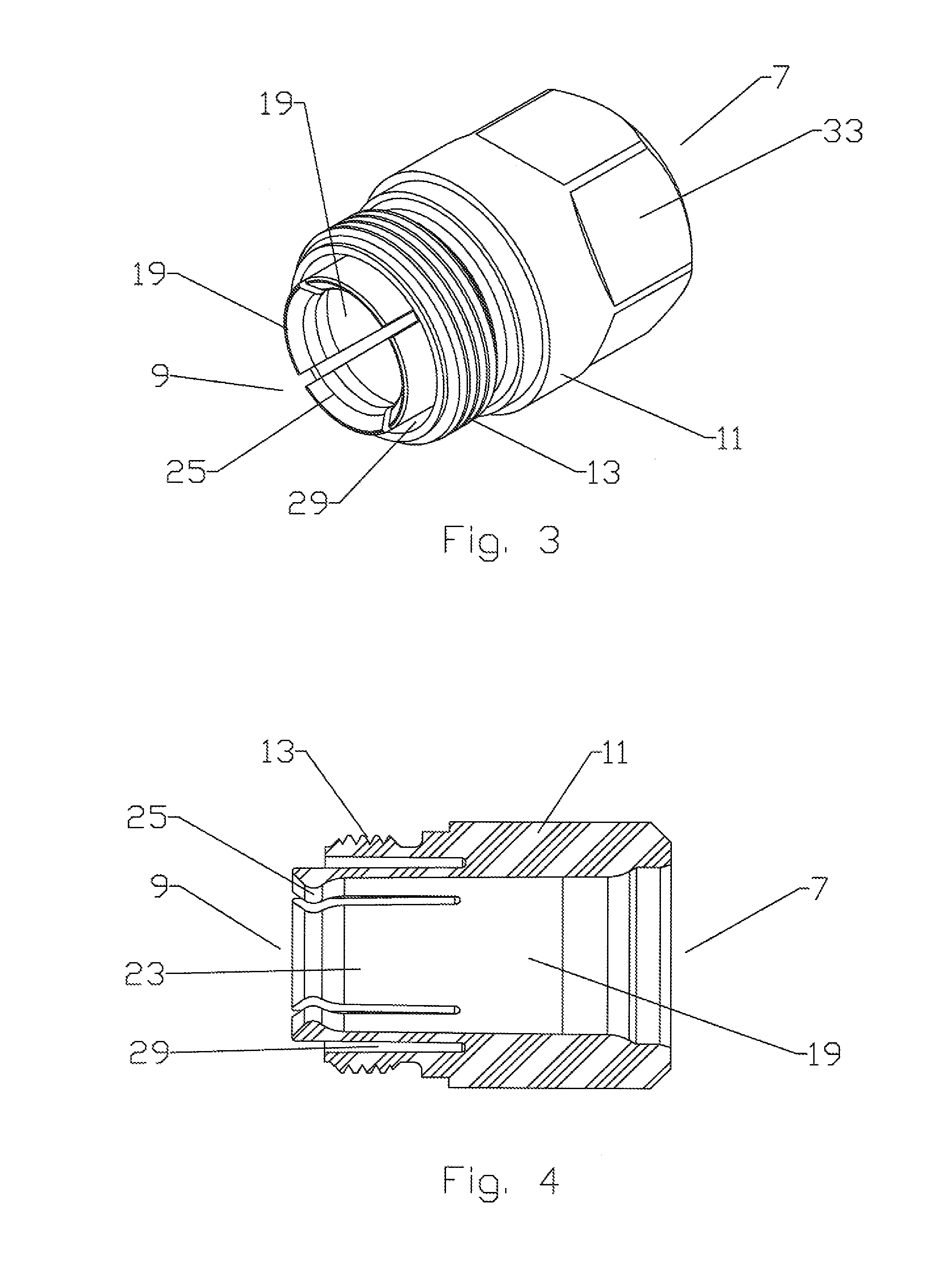
[0017]The inventor has recognized that a spring finger nut element of a connector according to the invention may be formed from a polymeric material via injection molding to eliminate the numerous required metal machining steps and significantly reduce materials costs and component weight. Although the connector body of a connector according to the invention may also be formed partially or completely from polymeric material, for example via overmolding or application of an internal conductive coating or separate internal conductive element, where only the metal spring finger nut is formed from polymeric material, the requirement for and associated complexities of an additional internal outer conductor conductive structure is eliminated.
[0018]The invention will be described in detail with respect to FIGS. 1-7, demonstrating an exemplary embodiment having a standard Type-N connector interface 1 for use with an annular corrugated solid outer conductor coaxial cable 3. One skilled in th...
PUM
| Property | Measurement | Unit |
|---|---|---|
| outer diameter | aaaaa | aaaaa |
| inner diameter | aaaaa | aaaaa |
| diameter | aaaaa | aaaaa |
Abstract
Description
Claims
Application Information