Contoured cortical bone implants

a cortical bone and implant technology, applied in the field of interbody spinal implants, can solve the problems of limited success of interbody spinal fusion with diaphyseal bone rings in the pas

Inactive Publication Date: 2008-10-14
WARSAW ORTHOPEDIC INC
View PDF145 Cites 169 Cited by
  • Summary
  • Abstract
  • Description
  • Claims
  • Application Information

AI Technical Summary

Problems solved by technology

Interbody spinal fusion with diaphyseal bone rings, however, has had limited success in the past.
While all the causes for failure may not yet be appreciated, it is nevertheless believed that a failure to gain congruity at the in...

Method used


Image

  • Contoured cortical bone implants
  • Contoured cortical bone implants
  • Contoured cortical bone implants

Examples


Embodiment Construction

[0045]The following description is intended to be representative only and not limiting and many variations can be anticipated according to these teachings, which are included within the scope of this inventive teaching. Reference will now be made in detail to the preferred embodiments of this invention, examples of which are illustrated in the accompanying drawings. Wherever possible, the same reference numbers will be used throughout the drawings to refer to the same or like parts.

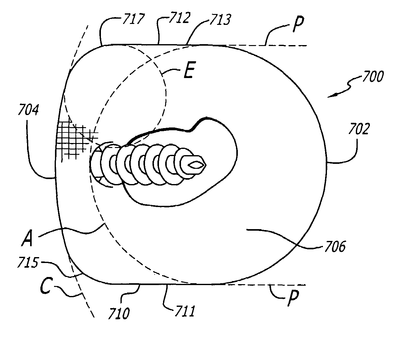
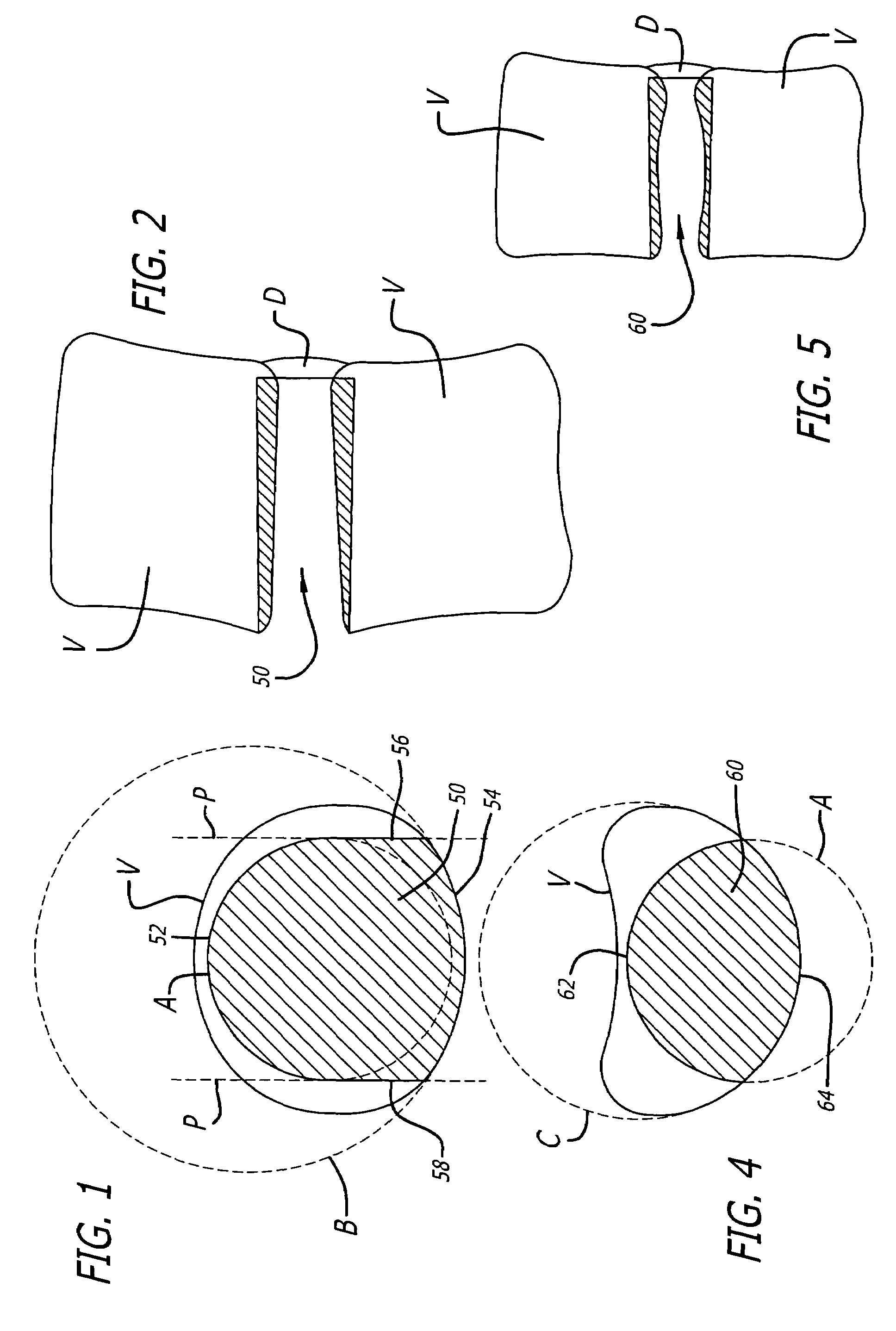
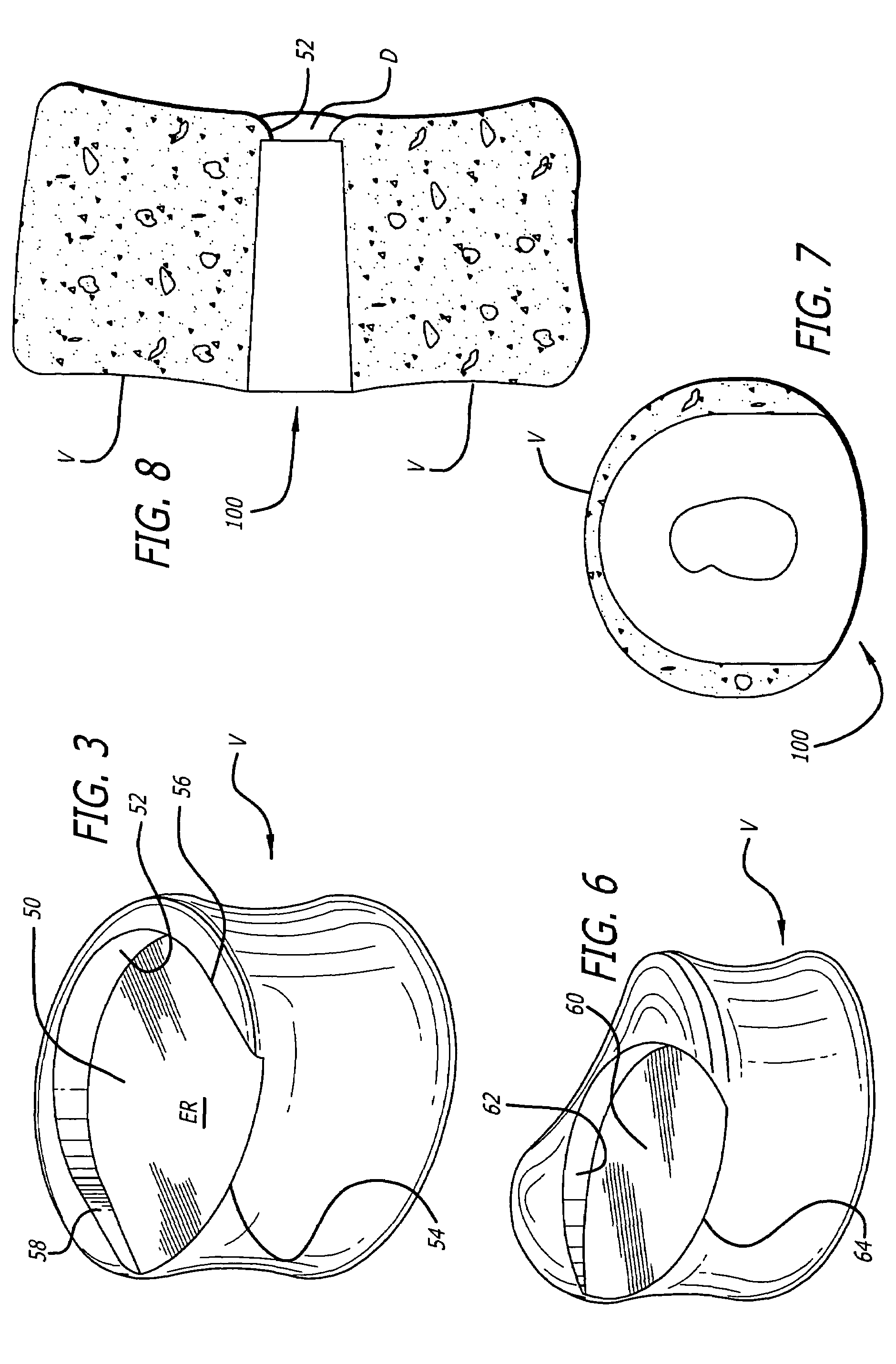
[0046]FIGS. 1-3 show an implantation space 50 formed across the height of the space occupied by a spinal disc D and into vertebral bodies V in the lumbar spine. Implantation space 50 is preferably formed with the apparatus and method disclosed by Michelson in U.S. Pat. No. 6,083,228, and WO 99 / 63891, the disclosures of which are both incorporated herein by reference. The instruments and method are not the subject matter of this application. It is understood that the preparation of the implantation space s...


PUM

PropertyMeasurementUnit
Lengthaaaaaaaaaa
Lengthaaaaaaaaaa
Lengthaaaaaaaaaa

Abstract

An interbody spinal implant made of cortical bone or a bone composite adapted for placement across an intervertebral space formed across the height of a disc space between two adjacent vertebral bodies. The implant has a leading end that includes at least a portion of an arc of a circle from side to side, and sides that are at least in part straight or a trailing end having a radius of curvature of another circle from side to side.

Description

RELATED APPLICATIONS[0001]This application is a continuation of application Ser. No. 10 / 112,746, filed Apr. 2, 2002, now U.S. Pat. No. 6,749,636; which claims the benefit of U.S. provisional Application No. 60 / 281,187, filed Apr. 3, 2001, and U.S. provisional Application No. 60 / 281,112, filed Apr. 2, 2001; all of which is incorporated by reference herein.FIELD OF THE INVENTION[0002]The present invention relates generally to interbody spinal implants preferably adapted for placement into an implantation space created across the height of a disc space between two adjacent vertebral bodies for the purpose of correcting spinal disease at that interspace. The spinal implants are made of an implant material that is bone or a bone composite. The implants are adapted such that fusion occurs at least in part through the implants.DESCRIPTION OF THE RELATED ART[0003]The diaphysis is the shaft of a major long bone between the epiphyses, the ends of the bone forming the joints. Human cadaveric d...

Claims


Application Information

Patent Timeline
IPC IPC(8): A61F2/44A61B17/86A61F2/00A61F2/02A61F2/28A61F2/30A61F2/46
CPCA61F2/28A61F2/4455A61B17/86A61F2/30767A61F2/3094A61F2/30965A61F2/4611A61F2002/2817A61F2002/2835A61F2002/30062A61F2002/30131A61F2002/30192A61F2002/30507A61F2002/30517A61F2002/30677A61F2002/30774A61F2002/30779A61F2002/30785A61F2002/30787A61F2002/30836A61F2002/30841A61F2002/30904A61F2002/4475A61F2002/448A61F2210/0004A61F2220/0025A61F2230/0013A61F2230/0041A61F2310/00017A61F2310/00023A61F2310/00029A61F2310/00131A61F2310/00179A61F2310/00293Y10S606/907Y10S606/908Y10S606/909A61F2002/30593
Inventor MICHELSON, GARY K
Owner WARSAW ORTHOPEDIC INC
Why Eureka
Try Eureka