Plasma arc torch

a technology of arc torch and arc plate, which is applied in the direction of gas-filled discharge tube, manufacturing tools, solventing apparatus, etc., can solve the problems of achieve the effect of improving safety features and preventing the operation of the torch

Active Publication Date: 2008-10-14
THE ESAB GROUP
View PDF6 Cites 33 Cited by
  • Summary
  • Abstract
  • Description
  • Claims
  • Application Information

AI Technical Summary

Benefits of technology

[0011]A first sealing member is operably engaged with the piston member and is configured to movably seal the piston member with respect to the bore, so as to allow the fluid flow to act upon the piston member to move the electrode to the torch operable position when the nozzle is operably engaged with the one end of the tubular member. A second sealing member is operably engaged with the bore and is configured to engage the piston member when the nozzle is not operably engaged with the one end of the tubular member, and the electrode is directed toward the one end of the tubular member and axially outward of the bore. The second sealing member is operably engaged with the bore such that the fluid flow inlet is disposed between the first and second sealing members. Such a configuration thereby prevents operation of the torch when the nozzle or electrode is not properly assembled therewith by preventing the fluid flow from acting upon the piston member to move the electrode to the torch operable position.
[0012]Embodiments of the present invention thus provide a blowback type of plasma arc torch having improved safety features, for example, by providing components configured to be formed into a torch assembly in a precise and consistent manner, whereby proper and complete assembly or reassembly of the torch may be readily assured and / or may be required before the torch can be operated. These and other significant advantages are provided by embodiments of the present invention, as described further herein.

Problems solved by technology

Such a configuration thereby prevents operation of the torch when the nozzle or electrode is not properly assembled therewith by preventing the fluid flow from acting upon the piston member to move the electrode to the torch operable position.

Method used


Image

  • Plasma arc torch
  • Plasma arc torch
  • Plasma arc torch

Examples


Embodiment Construction

[0016]The present inventions now will be described more fully hereinafter with reference to the accompanying drawings, in which some, but not all embodiments of the invention are shown. Indeed, these inventions may be embodied in many different forms and should not be construed as limited to the embodiments set forth herein; rather, these embodiments are provided so that this disclosure will satisfy applicable legal requirements. Like numbers refer to like elements throughout.

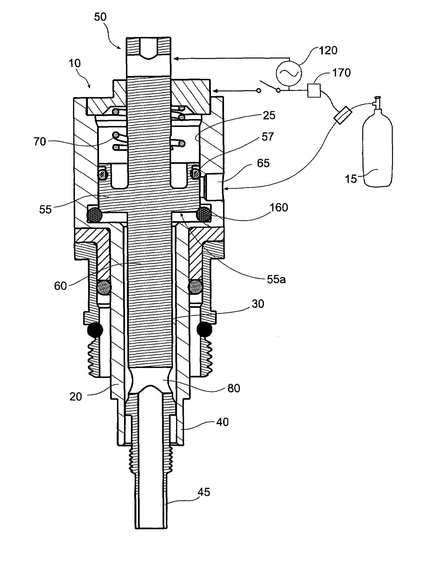
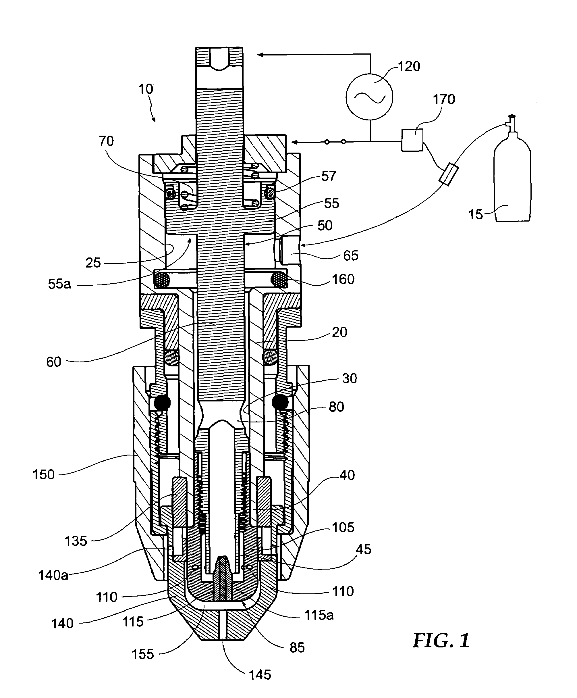
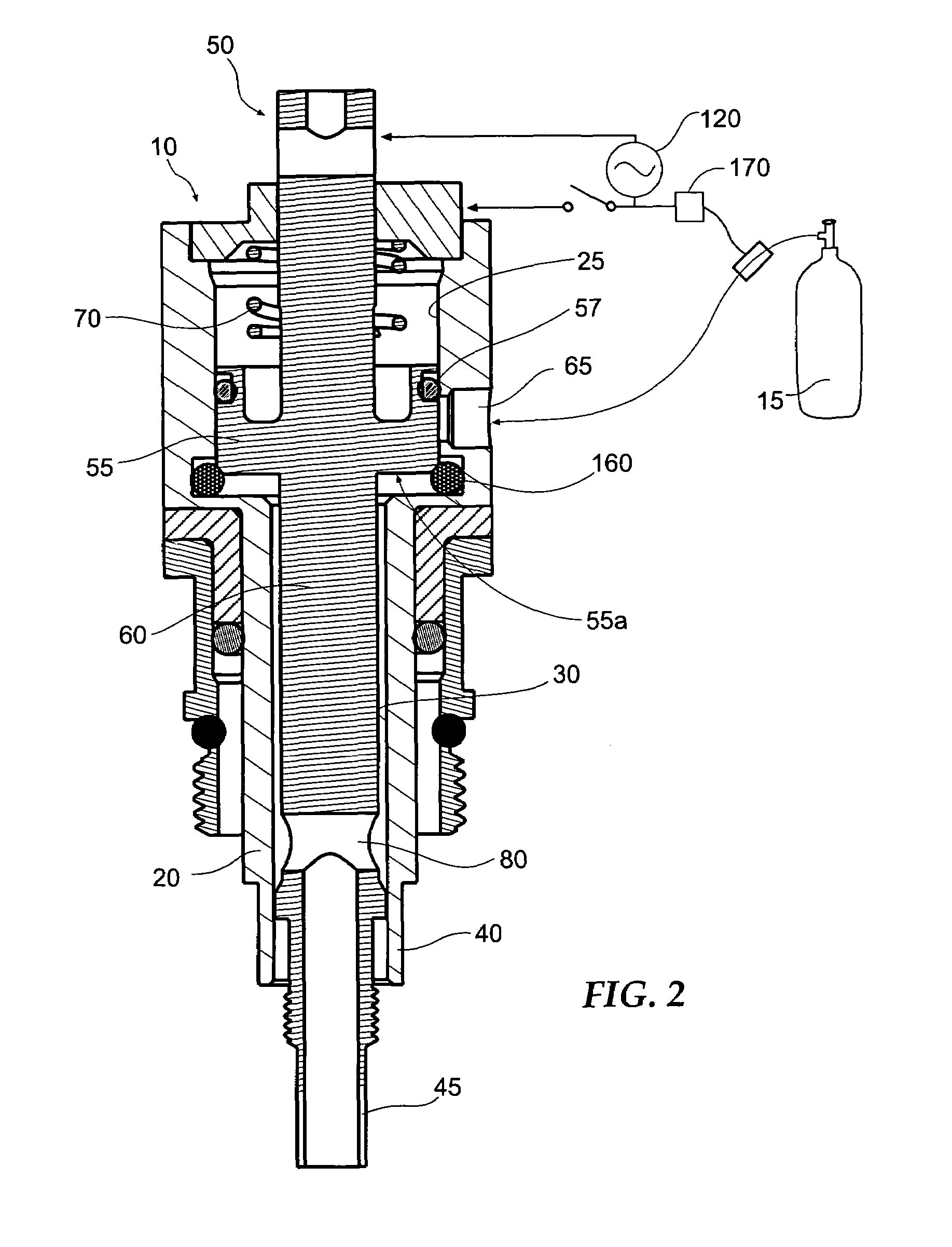
[0017]FIG. 1 illustrates a plasma arc torch according to one embodiment of the present invention, the torch being shown in an assembled condition and being indicated generally by the numeral 10. Such a torch 10 may be, for example, a blowback or touch-start type torch incorporating improved safety provisions. As shown, the torch 10 includes a tubular member or housing 20 defining a bore comprising, for example, axial piston bore 25 extending to a smaller axial shaft bore 30 along an axis. The shaft bore 30 ends...


PUM

PropertyMeasurementUnit
electrical currentaaaaaaaaaa
pressureaaaaaaaaaa
sizeaaaaaaaaaa

Abstract

A plasma torch is provided having a movable member carrying an electrode and movable along a tubular member bore having a nozzle at one end. A piston member engaged with the movable member moves the electrode between inoperable and operable positions within the bore, the movable member being biased outwardly of the one end of the bore. A first sealing member engaged with the piston member allows a fluid flow into the bore to act on the piston member to move the electrode to the operable position when the nozzle / electrode is engaged with the tubular member. A second sealing member, engaged with the bore, engages the piston member when the nozzle / electrode is removed. The fluid flow enters the bore between the sealing members, the second sealing member thus preventing torch operation when the nozzle / electrode is removed by preventing the fluid flow from acting on the piston.

Description

CROSS-REFERENCES TO RELATED APPLICATIONS[0001]This application is a continuation-in-part of U.S. patent application Ser. No. 11 / 043,687, filed on Jan. 26, 2005, now U.S. Pat. No. 7,105,770 which is hereby incorporated herein in its entirety by reference.BACKGROUND OF THE INVENTION[0002]1. Field of the Invention[0003]The present invention relates to a plasma arc torch and, more particularly, to a plasma arc torch with improved safety provisions.[0004]2. Description of Related Art[0005]Blowback type plasma torches are generally configured such that an electrode and a nozzle can be brought into contact with each other to ignite an arc, whereafter, the electrode is separated from the nozzle so as to draw the arc therebetween. A fluid, such as air, is concurrently provided under pressure through the nozzle, wherein the air flow interacts with the drawn arc so as to form a plasma. The plasma flowing through the nozzle is then directed at a workpiece to perform a cutting function.[0006]In ...

Claims


Application Information

Patent Timeline
Patent Type & Authority Patents(United States)
IPC IPC(8): B23K10/00
CPCH05H1/34H05H2001/3489H05H1/3489H05H1/26H05H1/38B23K10/00
Inventor GRIFFIN, DAVID C.
Owner THE ESAB GROUP
Why Eureka
Try Eureka