Methods for measuring optical characteristics by differential diffractive scanning

a technology of optical characteristics and scanning methods, applied in the direction of refractive surface testing, counting objects on conveyors, instruments, etc., can solve the problems of affecting the performance of articles, affecting the optical quality of articles, and requiring relatively expensive equipment for interferometer systems

Inactive Publication Date: 2008-10-14
AKONIA HOLOGRAPHICS
View PDF13 Cites 16 Cited by
  • Summary
  • Abstract
  • Description
  • Claims
  • Application Information

AI Technical Summary

Problems solved by technology

For example, optically flat surfaces may have desired tolerances relating to the smoothness and relative size of defects on the surface, where variations from the desired tolerances degrade the article performance.
Interferometer systems and methods have several disadvantages for inspecting the optical quality of articles.
For example, the interferometer system includes relatively expensive equipment, and generally must be dimensionally stable to less than the wavelength of the light being used in order to accurately observe the interference fringes.
The reference object is therefore generally made to high precision standards, often at substantial cost.
Also, fine-pitched features (e.g., surface roughness) are generally not well resolved with interferometer methods and systems.
Finally, interferometer methods generally do not allow for inspection or measurements of characteristics of the volume of the optical article, e.g., to determine index homogeneity or other characteristics at image planes within one or more layers of a transmissive and / or reflective optical article.

Method used


Image

  • Methods for measuring optical characteristics by differential diffractive scanning
  • Methods for measuring optical characteristics by differential diffractive scanning
  • Methods for measuring optical characteristics by differential diffractive scanning

Examples


Embodiment Construction

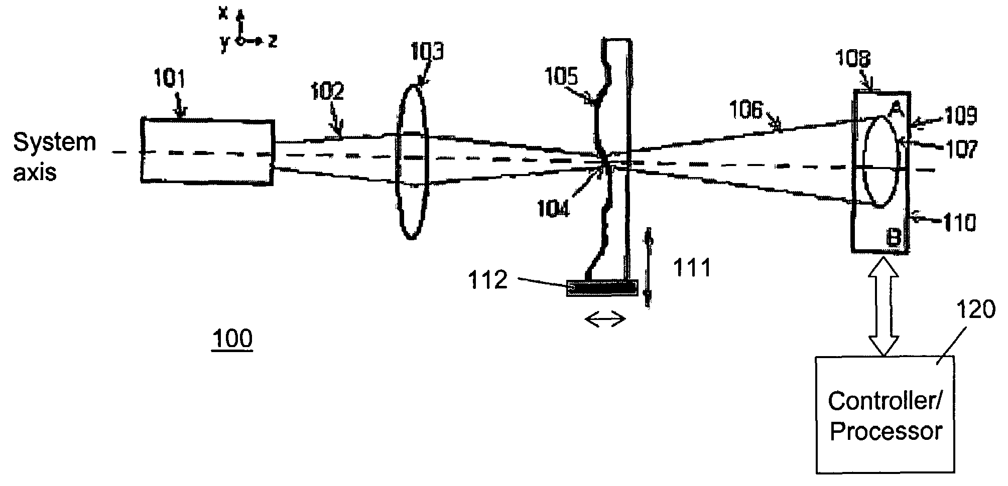
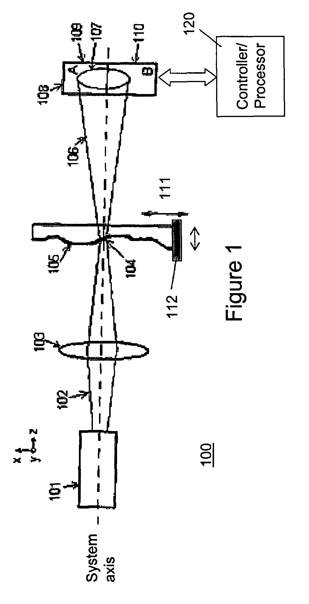
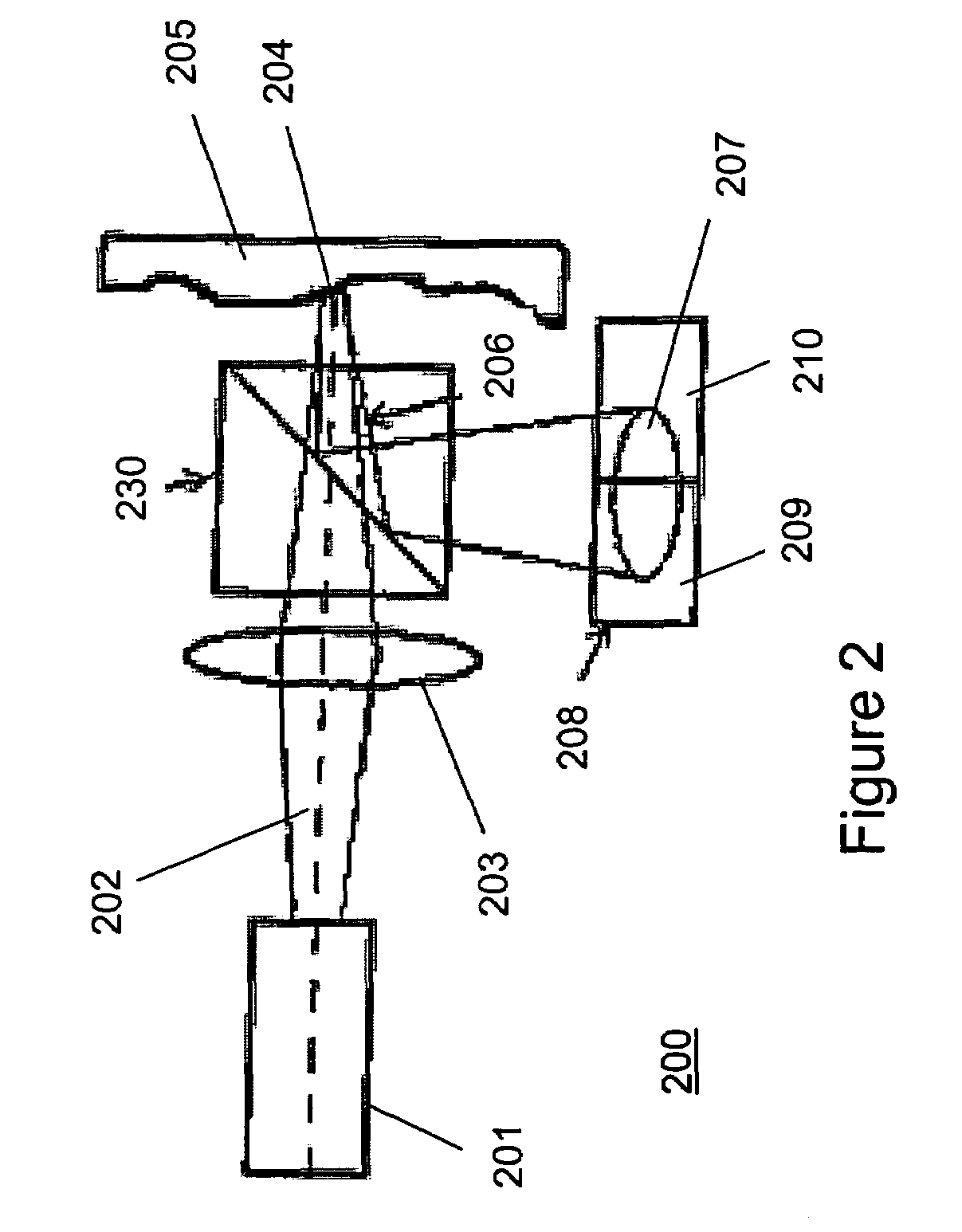
[0024]Methods and systems are provided for measuring optical characteristics of optical articles such as surface flatness, surface defects, volume index variations, and the like through differential diffractive measurements and scanning. The following description is presented to enable any person of ordinary skill in the art to make and use the invention. Descriptions of specific techniques and applications are provided only as examples. Various modifications to the examples described herein will be readily apparent to those of ordinary skill in the art, and the general principles defined herein may be applied to other examples and applications without departing from the spirit and scope of the invention. Thus, the present invention is not intended to be limited to the examples described and shown, but is to be accorded the widest scope consistent with the principles and features disclosed herein.

[0025]In one example of a differential diffractive scanning technique, a probe beam of ...


PUM

PropertyMeasurementUnit
diameteraaaaaaaaaa
diameteraaaaaaaaaa
heightaaaaaaaaaa

Abstract

Methods and systems for measuring and / or inspecting a characteristic of an optical article are provided. In one example, a method includes illuminating an optical article with a focused beam of light, detecting the light with a sensor after interacting with the optical article, determining a deflection angle of the beam of light, and determining a characteristic of the optical article based on the deflection angle. In one example, a system includes a light source, an optical element, and a sensor. The optical element focuses light from the light source to a reference location, the sensor detects the light from the reference location and generates signals associated with the intensity and position of the light received. A processor may receive the signals from the sensor and thereby determine a deflection angle of the light from the probe path.

Description

CROSS-REFERENCE TO RELATED APPLICATIONS[0001]The present application claims benefit of earlier filed provisional application U.S. Ser. No. 60 / 455,325, entitled “METHOD FOR MEASURING OPTICAL QUALITY BY DIFFERENTIAL DIFFRACTIVE SCANNING,” filed on Mar. 14, 2003, which is hereby incorporated by reference as if fully set forth herein.BACKGROUND[0002]1. Field of the Invention[0003]The invention relates generally to methods and systems for optical inspection and measurement techniques, and more particularly to methods and systems for inspecting and measuring surface and / or volume characteristics of transmissive and / or reflective optical articles.[0004]2. Description of the Related Art[0005]Many optical devices and systems include optical articles having desired optical characteristics and tolerances relating to, e.g., surface flatness and defect characteristics such as divots or peaks on optical surfaces as well as refractive index values of transmissive articles. The performance of an op...

Claims


Application Information

Patent Timeline
Patent Type & Authority Patents(United States)
IPC IPC(8): H01J40/14G01M11/00G01N21/41G01N21/47G11B7/0065G11B7/135
CPCG01M11/005G01N21/41G01N21/4788G11B7/0065G11B2007/13727
Inventor AYRES, MARK R.
Owner AKONIA HOLOGRAPHICS
Why Eureka
Try Eureka