Method for controlling stage apparatus

a stage apparatus and control technology, applied in the direction of electric controllers, motor/generator/converter stoppers, dynamo-electric converter control, etc., can solve the problem of difficult to detect the position of the stage using the interferometer, and achieve the effect of reducing the pressure on the apparatus and reducing the complexity

Inactive Publication Date: 2008-10-14
CANON KK
View PDF12 Cites 48 Cited by
  • Summary
  • Abstract
  • Description
  • Claims
  • Application Information

AI Technical Summary

Benefits of technology

[0010]The present invention is directed to a method for, in a stage apparatus using a planar motor, facilitating the automatic return of a stage to a state at which a positional servo is available even when the positional servo becomes inoperative. Additionally, because an auxiliary unit (e.g., a robot hand) is not required, the pressure to upsize and complicate the apparatus can be reduced.

Problems solved by technology

However, if the stage is in a largely rotated state, it is difficult to detect the position of the stage using the interferometer.

Method used


Image

  • Method for controlling stage apparatus
  • Method for controlling stage apparatus
  • Method for controlling stage apparatus

Examples


first exemplary embodiment

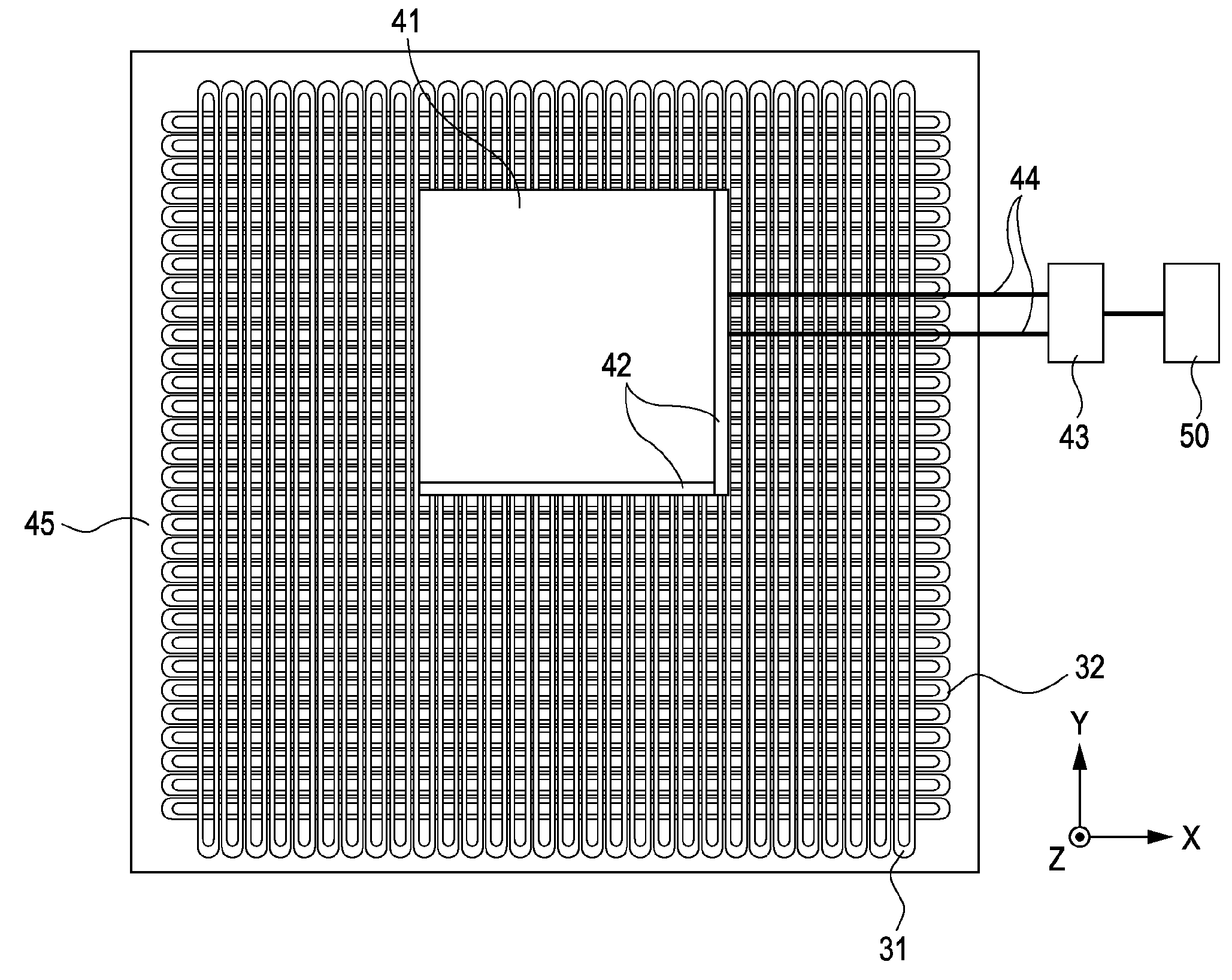
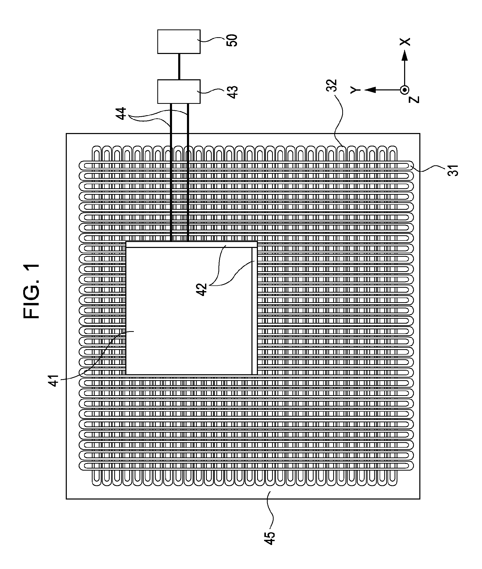
[0034]A general structure of a planar motor is substantially disclosed in U.S. Pat. No. 6,987,335 (corresponding to Japanese Patent Laid-Open No. 2004-254489) and will only briefly described below with reference to FIGS. 1 and 2A and 2B.

[0035]A stage apparatus includes a stage (movable element) 41, a mirror 42 disposed on the stage 41a laser interferometer 43 disposed outside stage 41, and a base (stator) 45 supporting stage 41. On an upper surface of stage 41, a wafer chuck (not shown) is disposed, and the wafer chuck holds a wafer. On a lower surface (underside) of stage 41, a plurality of permanent magnets is disposed. The plurality of permanent magnets is arranged so as to form periodical distribution of magnetic flux density.

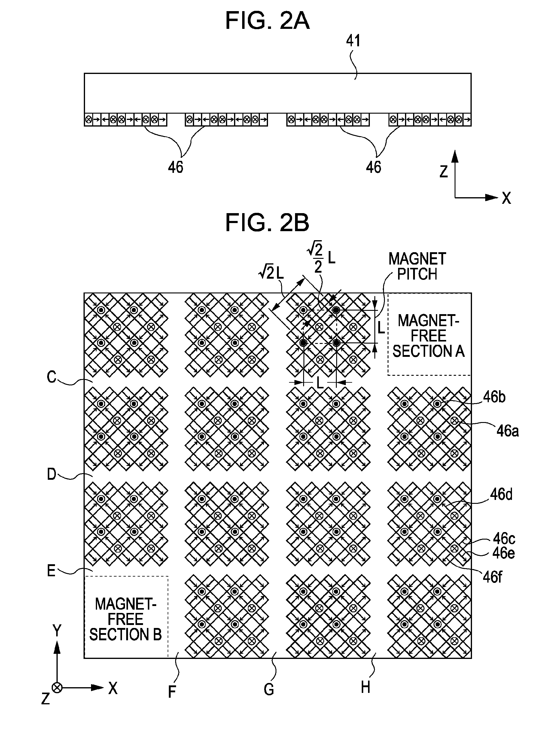
[0036]FIGS. 2A and 2B are illustrations for explaining the permanent magnets arranged on the lower surface of stage 41. FIG. 2A is a view as seen from the Y direction, and FIG. 2B is a view as seen from the −Z direction.

[0037]On the lower surface (underside...


PUM

PropertyMeasurementUnit
rotation angleaaaaaaaaaa

Abstract

At least one exemplary embodiment is directed to a control method for controlling a stage apparatus including a base and a stage, the base including first and second coil phases, the stage including a plurality of magnets. The control method includes a first energization step of rotating the stage to a stable angle by contemporaneously energizing a plurality of coils comprising the first coil phase and a second energization step of rotating the stage to a stable angle by sequentially energizing coils comprising the second coil phase one by one.

Description

BACKGROUND OF THE INVENTION[0001]1. Field of the Invention[0002]The present invention relates to a method for controlling a stage apparatus, and more specifically, though not exclusively, controlling a stage apparatus by using a planar motor.[0003]2. Description of the Related Art[0004]An exposure apparatus includes a wafer stage for facilitating the placement of a wafer thereon and to move the wafer. To drive such a stage, the use of a planar motor has received attention in recent years. FIGS. 1, 2A, and 2B illustrate a wafer stage using a planar motor as discussed in U.S. Pat. No. 6,987,335 (corresponding to Japanese Patent Laid-Open No. 2004-254489).[0005]In FIGS. 2A and 2B, a plurality of magnets are disposed on a lower surface of a stage (movable element), and a plurality of coils are disposed on a base (stator). The stage is moved with respect to the base by the Lorentz force generated by energizing the coils through which magnetic flux generated by the magnets passes.[0006]A ...

Claims


Application Information

Patent Timeline
Patent Type & Authority Patents(United States)
IPC IPC(8): H02P1/00H01L21/027G03F7/20H01L21/68H02P25/06
CPCH01L21/682H02K41/03H02P25/06H02K2201/18
Inventor MIYAKAWA, TAKAHIRO
Owner CANON KK
Why Eureka
Try Eureka