Electronic image pickup system

a pickup system and electronic technology, applied in the field of electronic image pickup systems, can solve the problems of difficult to make the second lens group itself thin, difficult to make aberration correction, and difficult to make the depth dimension of the camera thin, so as to reduce the depth dimension, reduce the restrictive conditions for the zooming movement of the moving lens group, and achieve the effect of high specification requirements

Active Publication Date: 2008-10-14
OLYMPUS OPTICAL CO LTD +1
View PDF43 Cites 16 Cited by
  • Summary
  • Abstract
  • Description
  • Claims
  • Application Information

AI Technical Summary

Benefits of technology

[0009]In view of such problems with the prior art as referred to above, the primary object of the present invention is to provide an electronic image pickup system with extremely diminished depth dimension, which makes use of a rear focus type zoom lens wherein the optical path (optical axis) of an optical system is bent with a reflecting optical element such as a mirror, and restrictive conditions for the zooming movement of a moving lens group can be substantially eliminated while maintaining high specification requirements and improved performance.

Problems solved by technology

The gravest bottleneck in making the depth dimension of cameras thin is the thickness of an optical system, especially a zoom lens from the surface located nearest to the object side to the image pickup plane.
Thus, it is not only difficult to make the second lens group itself thin but it is also difficult to make correction for aberrations.
In addition, the influence of production errors grows.
To ensure the same number of pixels, however, the pixel pitch must be diminished and insufficient sensitivity must be covered by the optical system.
Alternatively, such thickness reductions may be achieved by bending the optical path of an optical system with a mirror or the like; however, some considerable restrictions are imposed on the zooming movement of lenses because of the space for such optical path bending.

Method used


Image

  • Electronic image pickup system
  • Electronic image pickup system
  • Electronic image pickup system

Examples


example 1

[0155]

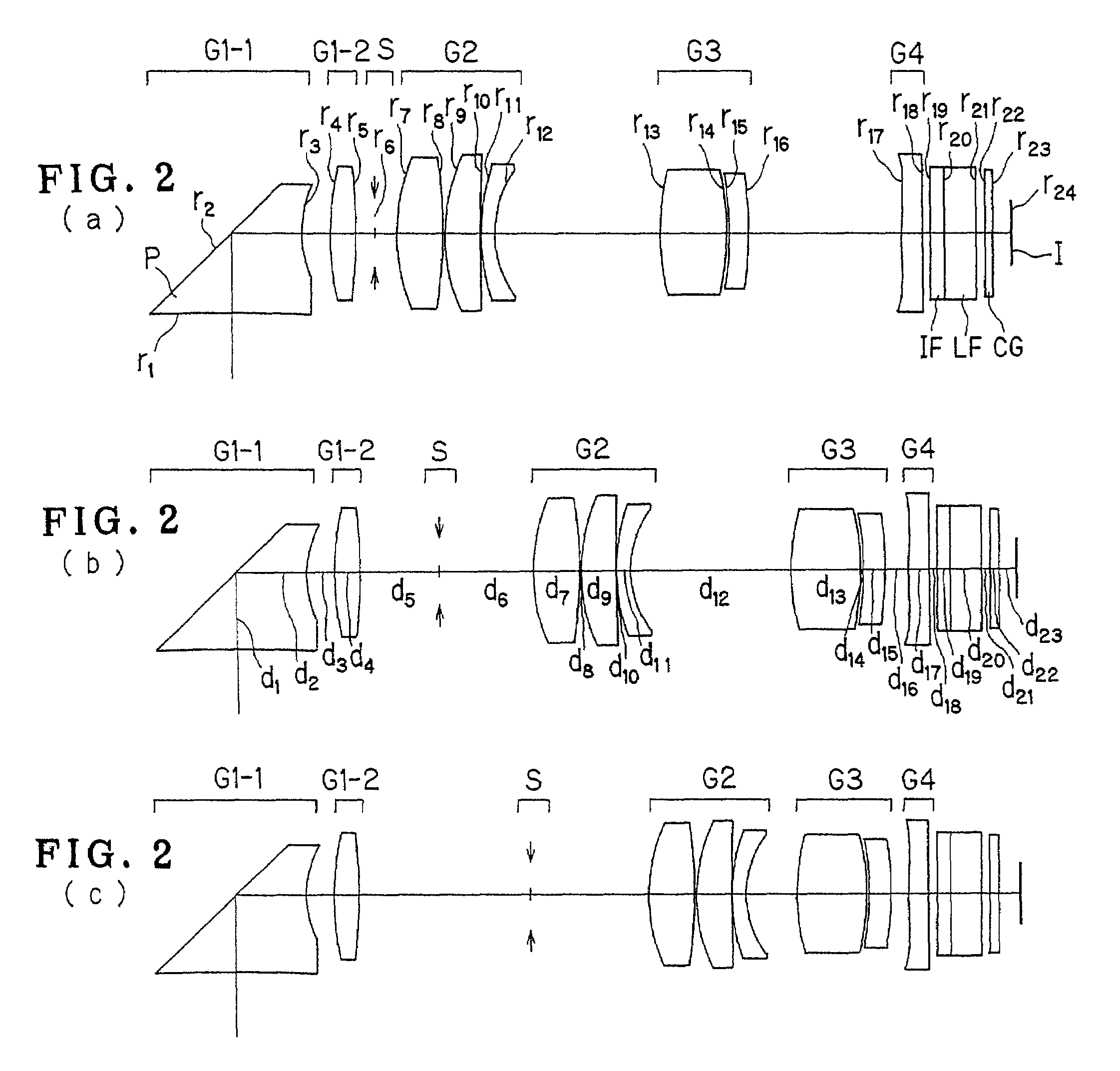
r1 = −26.8147d1 = 3.8000nd1 = 1.73400νd1 = 51.47r2 = ∞ (Mirror)d2 = 3.2000nd2 = 1.73400νd2 = 51.47r3 = 6.2254d3 = 1.7202r4 = 424.9864d4 = 2.4297nd3 = 1.84666νd3 = 23.78(Aspheric)r5 = −48.1247d5 = (Variable)r6 = ∞ (Stop)d6 = 0.5000r7 = 17.8731d7 = 2.0000nd4 = 1.58913νd4 = 61.26(Aspheric)r8 = −16.6911d8 = (Variable)r9 = 7.9903d9 = 6.2379nd5 = 1.48749νd5 = 70.23r10 = −14.7007d10 = 0.8488nd6 = 1.84666νd6 = 23.78r11 = 7.0178d11 = 1.1903r12 = 11.2307d12 = 1.6307nd7 = 1.84666νd7 = 23.78r13 = −24.5400d13 = (Variable)r14 = 18.1763d14 = 0.5000nd8 = 1.84666νd8 = 23.78r15 = 5.9110d15 = (Variable)(Aspheric)r16 = 14.1876d16 = 3.0000nd9 = 1.58913νd9 = 61.26r17 = −7.1178d17 = 0.5006(Aspheric)r18 = ∞d18 = 0.8000nd10 = 1.51633νd10 = 64.14r19 = ∞d19 = 1.8000nd11 = 1.54771νd11 = 62.84r20 = ∞d20 = 0.5000r21 = ∞d21 = 0.5000nd12 = 1.51633νd12 = 64.14r22 = ∞d22 = 1.1914r23 = ∞(Image Plane)Aspherical Coefficients4th surfaceK = 0.0195A4 = −5.4111 × 10⁻⁴A6 = 2.1984 × 10⁻⁶A8 = 4.5957 × 10⁻⁷A10 = −1.0754 ...

example 2

[0156]

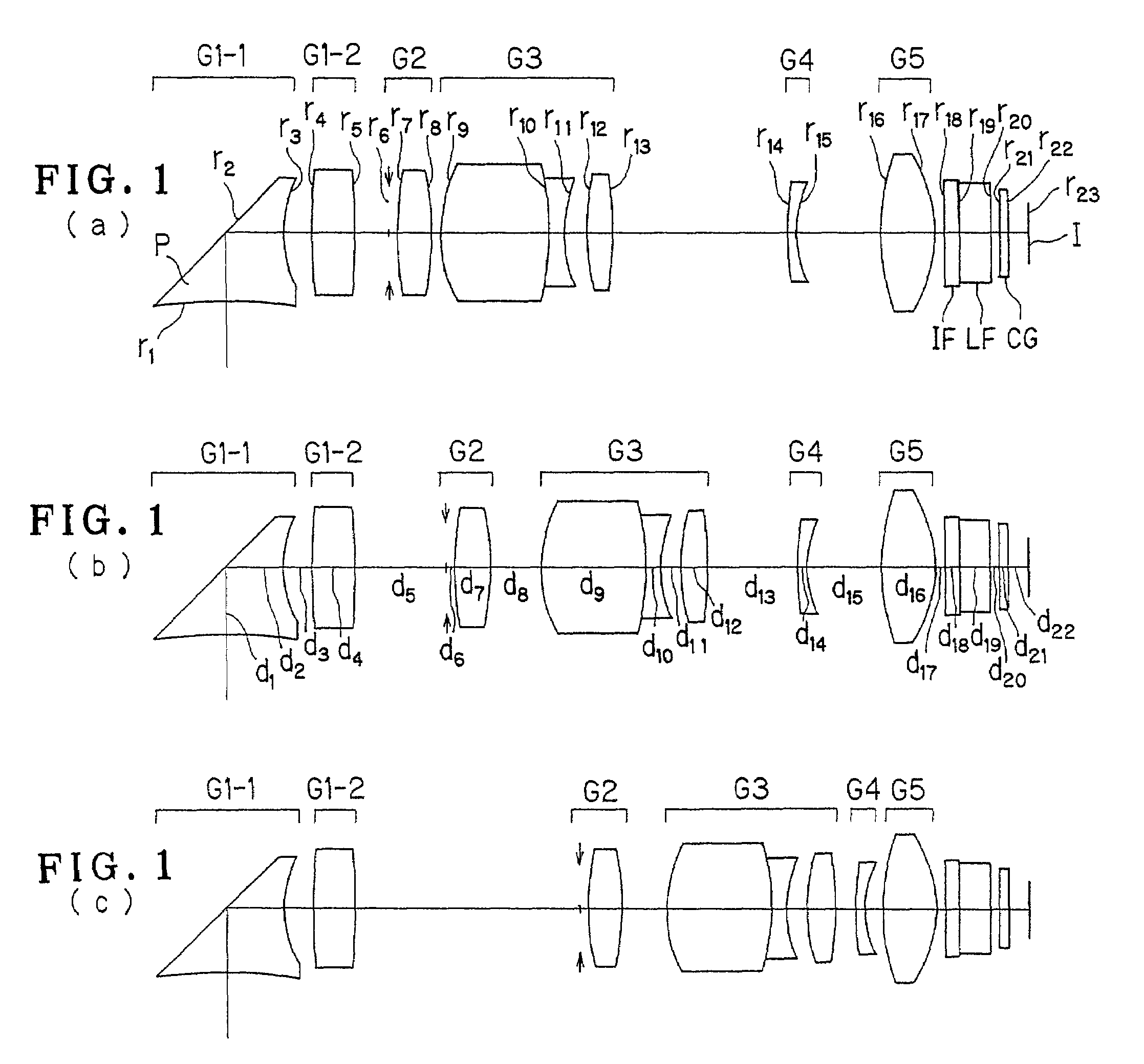
r1 = −129.7294d1 = 4.5500nd1 = 1.80400νd1 = 46.57r2 = ∞ (Mirror)d2 = 4.0019nd2 = 1.80400νd2 = 46.57r3 = 5.3898d3 = 1.6465r4 = 30.0332d4 = 1.4609nd3 = 1.84666νd3 = 23.78(Aspheric)r5 = −35.8611d5 = (Variable)r6 = ∞ (Stop)d6 = (Variable)r7 = 9.6063d7 = 2.7296nd4 = 1.48749νd4 = 70.23(Aspheric)r8 = −30.8421d8 = 0.1469r9 = 10.1172d9 = 2.1277nd5 = 1.69680νd5 = 55.53r10 = 97.1974d10 = 0.0500r11 = 12.1982d11 = 0.7949nd6 = 1.84666νd6 = 23.78r12 = 5.7271d12 = (Variable)r13 = 14.2960d13 = 4.0342nd7 = 1.48749νd7 = 70.23r14 = −15.7323d14 = 0.1401r15 = −18.5671d15 = 1.1241nd8 = 1.84666νd8 = 23.78r16 = −29.8834d16 = (Variable)r17 = 46.3841d17 = 1.1752nd9 = 1.58913νd9 = 61.26(Aspheric)r18 = 541.6142d18 = 0.4453r19 = ∞d19 = 0.8000nd10 = 1.51633νd10 = 64.14r20 = ∞d20 = 1.8000nd11 = 1.54771νd11 = 62.84r21 = ∞d21 = 0.5000r22 = ∞d22 = 0.5000nd12 = 1.51633νd12 = 64.14r23 = ∞d23 = 1.2588r24 = ∞(Image Plane)Aspherical Coefficients4th surfaceK = 42.6072A4 = 4.5281 × 10⁻⁴A6 = −1.2752 × 10⁻⁸A8 = 2.9327 ×...

example 3

[0157]

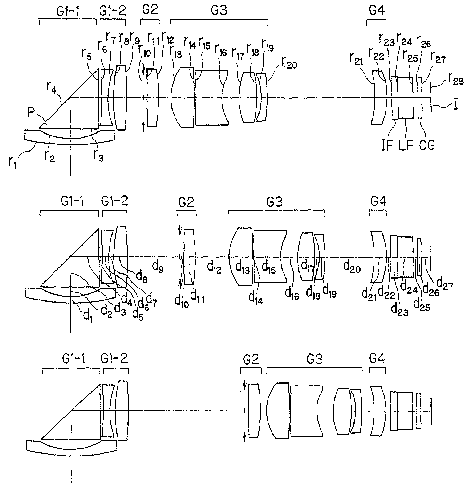
r1 = 22.0799d1 = 0.7823nd1 = 1.80400νd1 = 46.57r2 = 7.0105d2 = 1.1905r3 = ∞d3 = 3.8000nd2 = 1.80400νd2 = 46.57r4 = ∞ (Mirror)d4 = 3.4483nd3 = 1.80400νd3 = 46.57r5 = ∞d5 = 0.4000r6 = −43.4610d6 = 0.7742nd4 = 1.77250νd4 = 49.60r7 = 9.6384d7 = 0.6369r8 = 19.1908d8 = 1.6810nd5 = 1.84666νd5 = 23.78(Aspheric)r9 = −40.1274d9 = (Variable)r10 = ∞ (Stop)d10 = 0.5000r11 = 85.1662d11 = 1.5117nd6 = 1.58913νd6 = 61.26r12 = −18.3807d12 = (Variable)r13 = 5.5347d13 = 2.9473nd7 = 1.48749νd7 = 70.23(Aspheric)r14 = −102.8346d14 = 0.1500r15 = 68.5128d15 = 3.4582nd8 = 1.84666νd8 = 23.78r16 = 5.6774d16 = 2.1376r17 = 7.8453d17 = 2.3148nd9 = 1.60542νd9 = 45.99r18 = −12.6010d18 = 0.5441r19 = −6.0465d19 = 0.7255nd10 = 1.61800νd10 = 63.33r20 = −17.9513d20 = (Variable)r21 = −17.2238d21 = 1.4117nd11 = 1.58913νd11 = 61.26(Aspheric)r22 = −9.8048d22 = 0.5599r23 = ∞d23 = 0.8000nd12 = 1.51633νd12 = 64.14r24 = ∞d24 = 1.8000nd13 = 1.54771νd13 = 62.84r25 = ∞d25 = 0.5000r26 = ∞d26 = 0.5000nd14 = 1.51633νd14 = 64.1...


PUM


Abstract

The invention relates to an electronic image pickup system whose depth dimension is extremely reduced, taking advantage of an optical system type that can overcome conditions imposed on the movement of a zooming movable lens group while high specifications and performance are kept. The electronic image pickup system comprises an optical path-bending zoom optical system comprising, in order from its object side, a 1-1st lens group G1-1 comprising a negative lens group and a reflecting optical element P for bending an optical path, a 1-2nd lens group G1-2 comprising one positive lens and a second lens group G2 having positive refracting power. For zooming from the wide-angle end to the telephoto end, the second lens group G2 moves only toward the object side. The electronic image pickup system also comprises an electronic image pickup device I located on the image side of the zoom optical system.

Description

[0001]This application claims benefits of Japanese Application No. 2001-142948 filed in Japan on May 14, 2001, the contents of which are incorporated by this reference.BACKGROUND OF THE INVENTION[0002]The present invention relates generally to a slim electronic image pickup system comprising an optical path-bending zoom optical system, and particularly to an image pickup system inclusive of video cameras or digital cameras, the depth dimension of which is reduced by contriving an optical system portion thereof, e.g., a zoom lens.[0003]In recent years, digital cameras (electronic cameras) have received attention as cameras of the next generation, an alternative to silver-salt 35 mm-film (usually called Leica format) cameras. Currently available digital cameras are broken down into some categories in wide ranges from the high-end type for commercial use to the portable low-end type.[0004]In view of the portable low-end type category in particular, the primary object of the present inv...

Claims


Application Information

Patent Timeline
Patent Type & Authority Patents(United States)
IPC IPC(8): G02B15/14G02B17/00G02B13/00
CPCG02B13/0045G02B13/006G02B13/0065G02B15/14G02B13/0075G02B13/009G02B13/007G02B15/145123G02B15/144H04N23/55H04N23/54H04N23/69H04N23/698
Inventor MIHARA, SHINICHIKONISHI, HIROKAZUHANZAWA, TOYOHARUWATANABE, MASAHITOISHII, ATSUJIROTAKEYAMA, TETSUHIDEIMAMURA, AYAMI
Owner OLYMPUS OPTICAL CO LTD
Why Eureka
Try Eureka