Axially compact mechanical igniter for thermal batteries and the like

a technology of mechanical igniter and thermal battery, which is applied in the direction of ignitors, ammunition fuzes, electrical generators, etc., can solve the problems of high acceleration level and the inertial igniter to significantly lower the resulting impulse level

Active Publication Date: 2008-10-21
OMNITEK PARTNERS LLC +1
View PDF17 Cites 26 Cited by
  • Summary
  • Abstract
  • Description
  • Claims
  • Application Information

AI Technical Summary

Benefits of technology

[0022]A need therefore exists for the development of novel miniature inertial igniters for thermal batteries used in gun fired munitions, particularly for small and low power thermal batteries that could be used in fuzing and other similar applications, thereby eliminating the need for external power sources. The development of such novel miniature inertial ignition mechanism concepts also requires the identification or design of appropriate pyrotechnics. The innovative inertial igniters can be scalable to thermal batteries of various sizes, in particular to miniaturized igniters for small size thermal batteries. Such inertial igniters must be safe and in general and in particular they should not initiate if dropped, e.g., from up to 7 feet onto a concrete floor for certain applications; should withstand high firing accelerations, for example up to 20-50,000 Gs; and should be able to be designed to ignite at specified acceleration levels when subjected to such accelerations for a specified amount of time to match the firing acceleration experienced in a gun barrel as compared to high G accelerations experienced during accidental falls which last over very short periods of time, for example accelerations of the order of 1000 Gs when applied for 5 msec as experienced in a gun as compared to for example 2000 G acceleration levels experienced during accidental fall over a concrete floor but which may last only 0.5 msec. Reliability is also of much concern since the rounds should have a shelf life of up to 20 years and could generally be stored at temperatures of sometimes in the range of −65 to 165 degrees F. This requirement is usually satisfied best if the igniter pyrotechnic is in a sealed compartment. The inertial igniters must also consider the manufacturing costs and simplicity in design to make them cost effective for munitions applications.

Problems solved by technology

For example, an accidental drop may well cause very high acceleration levels—even in some cases higher than the firing of a shell from a gun.
However, the duration of this accidental acceleration will be short, thereby subjecting the inertial igniter to significantly lower resulting impulse levels.

Method used


Image

  • Axially compact mechanical igniter for thermal batteries and the like
  • Axially compact mechanical igniter for thermal batteries and the like
  • Axially compact mechanical igniter for thermal batteries and the like

Examples


Embodiment Construction

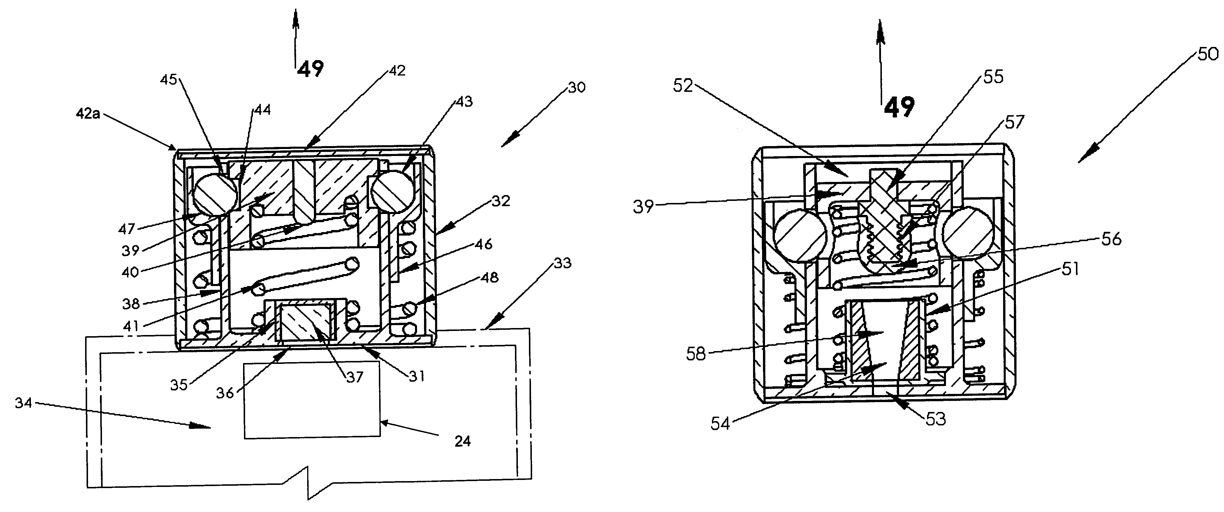
[0049]A schematic of a cross-section of a first embodiment 30 of an inertia igniter is shown in FIG. 4, referred to generally with reference numeral 30. The inertial igniter 30 is constructed with an igniter body 31 and a housing wall 32. In the schematic of FIG. 4, the igniter body 31 and the housing wall 32 are joined together at one end; however, the two components may be integrated as one piece. In addition, the base of the housing 31 may be extended to form the cap 33 of the thermal battery 34, the top portion of which is shown with dashed lines in FIG. 4. The base of the housing 31 is provided with a recess 35 to receive the percussion cap primer 37. The base of the housing 31 is also provided with the opening 36 within the recess 35 to allow the ignited sparks and fire to exit the primer 37 into the thermal battery 34 upon initiation of the percussion cap primer 37. The internal components of the inertial igniter 30 are sealed by a cap 42 which can be brazed or welded at seam...


PUM


Abstract

An inertial igniter including: a first member having a wall and internal cavity; a second member slidable in the internal cavity, a striker disposed thereon and a first concave portion; a third member slidable on an exterior surface of the wall, a second concave portion; biasing springs for biasing the first and second members in a direction opposite an acceleration; locking balls in the first and second concave portions for preventing movement of the second and third members when the acceleration time profile is below a predetermined threshold; and a percussion cap primer on the first member; wherein when the acceleration time profile is greater than the predetermined threshold the locking balls are released from the concave portions to first permit relative movement of the third member with the first member and after a time delay to permit relative movement of the second member with the first member.

Description

GOVERNMENT RIGHTS[0001]The U.S. Government has a paid-up license in this invention and the right in limited circumstances to require the patent owner to license others on reasonable terms as provided for by the terms of SBIR Grant No. DAAE30-03-C-1077 awarded by the Department of Defense on Jul. 17, 2006.BACKGROUND OF THE INVENTION[0002]1. Field of the Invention[0003]The present invention relates generally to mechanical igniters, and more particularly to axially compact mechanical igniters for thermal batteries and the like.[0004]2. Prior Art[0005]Thermal batteries represent a class of reserve batteries that operate at high temperatures. Unlike liquid reserve batteries, in thermal batteries the electrolyte is already in the cells and therefore does not require a distribution mechanism such as spinning. The electrolyte is dry, solid and non-conductive, thereby leaving the battery in a non-operational and inert condition. These batteries incorporate pyrotechnic heat sources to melt th...

Claims


Application Information

Patent Timeline
Patent Type & Authority Patents(United States)
IPC IPC(8): F42C15/24F42C15/34
CPCC06C9/00H01M6/36F42C15/24F42C15/20
Inventor RASTEGAR, JAHANGIR S.MURRAY, RICHARDCHEN, GARYHARTLEY, RAYMOND MICHAEL
Owner OMNITEK PARTNERS LLC
Why Eureka
Try Eureka