Electrically-powered autonomous vehicle

an electric-powered, autonomous vehicle technology, applied in the direction of vehicles, applications, propulsion by batteries/cells, etc., can solve the problems of large technological variation, rapid overtake, and inability to design autonomous vehicles with a large payload capability, etc., to achieve the effect of extending the range of the vehicl

Active Publication Date: 2008-10-21
SOC ALBIGEOISE DE FAB & DE REPARATION AUTOMOBILE SAFRA 50 INTEREST
View PDF19 Cites 6 Cited by
  • Summary
  • Abstract
  • Description
  • Claims
  • Application Information

AI Technical Summary

Benefits of technology

[0041]The battery chassis may furthermore be either equipped with a charger, allowing the batteries to be recharged wherever the charger can be plugged in to an electrical supply (the terminus or an intermediate stop along the line), or support an energy conversion device able to recharge the batteries. This device may be an alternator operated by a combustion engine or inertia flywheels, and this amounts to equipping the chassis with an electrical generator set capable of recharging the batteries on demand and therefore of extending the range of the vehicle.

Problems solved by technology

In spite of the availability of high-performance batteries (NiMH, lithium-ion, etc.), it is practically impossible to design autonomous vehicles with a large payload capability and which are “all electric”, because of the problems of storing the electricity and of the autonomy or range of the vehicle.
Furthermore, one serious obstacle to the introduction into service of electrically powered autonomous vehicles stems from the fact that the technological variation, in terms of batteries, is great, complex, expensive, rapidly surpassed and that the batteries usually require special equipment in servicing and repair shops.
These constraints are incompatible with the need of the operators concerned with the transport of individuals and / or goods who need to amortize their investments in rolling stock over a period of between 10 and 20 years.
Furthermore, even if the wheel were not a pivoting wheel, as in DE-A-42 05 327, the fact that there was only one wheel would present only disadvantages when applied to a connectable / disconnectable trailer:lack of stability when handling,the need to provide complicated, bulky and expensive guidance and suspension means,the difficulty of maintenance, andthe difficulty of repairing it should it experience a flat.
However, this design operates correctly only under ideal conditions because:when the trailer goes over a speed hump, it may be crushed by the chassis of the vehicle; andwhen starting a bend with a cross-fall, the chassis of the vehicle will become inclined transversely with respect to the trailer and considerable loadings will be applied to the trailer transverse guidance device.
In consequence, the operation of the device that forms the subject of DE-A-41 05 246 cannot be considered to be reliable.
The prior art (the aforementioned FR-A-2 482 528) also discloses the addition of a trailer, equipped with a two-wheeled axle, to a utility vehicle, but the size of this trailer is added to that of the vehicle, the result of this being a considerable loss of space when running around and at the depot.

Method used


Image

  • Electrically-powered autonomous vehicle
  • Electrically-powered autonomous vehicle
  • Electrically-powered autonomous vehicle

Examples


Embodiment Construction

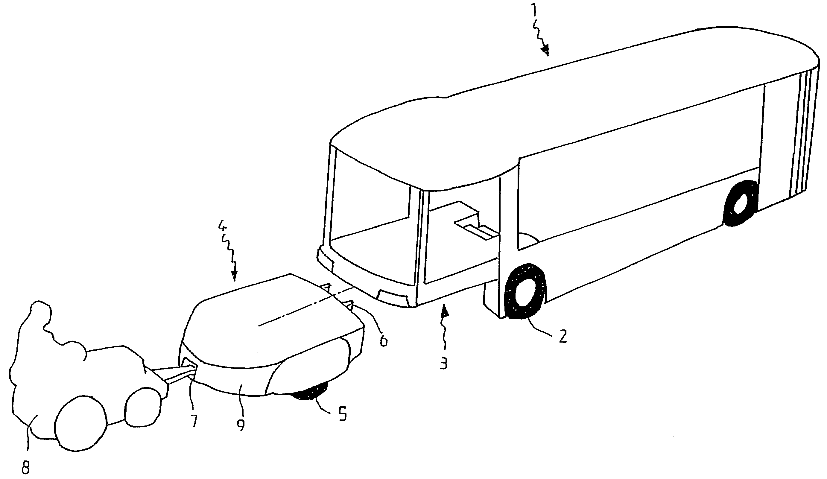
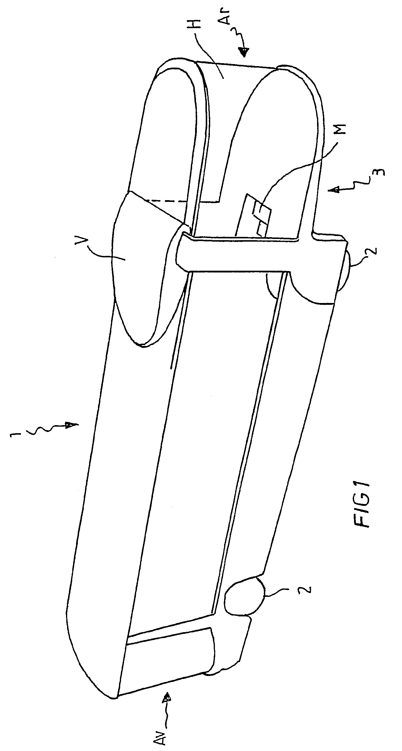
[0054]FIG. 1 depicts an electrically powered autonomous vehicle 1 comprising a chassis equipped with two axles each fitted with one pair of wheels 2, and the front of which is denoted by Av and the rear by Ar. The vehicle chassis defines, at the rear, a housing 3 situated under a raised cabin part H and designed to accommodate a battery chassis.

[0055]The vehicle motor is situated between the wheels of the vehicle (under the steps M of the stairs in the embodiment depicted) or, better still, in the wheels themselves (electric motorized wheels are known in the art and there is no need to describe these here). The volume V available on the roof may be used to house cooling devices, on-board computer equipment and / or an additional reserve of power. It is also possible for equipment specific to the use, for example air-conditioning means, alcohol-fired, gas-fired or fuel-fired heating means (in the current state of the art, electric vehicles are not generally electrically heated because ...


PUM

PropertyMeasurementUnit
volumeaaaaaaaaaa
diameteraaaaaaaaaa
diameteraaaaaaaaaa

Abstract

For power purposes, an electrically-powered autonomous vehicle requires a mass and/or a significant volume of batteries, the batteries being supported by an independent chassis (4). The independent chassis is designed to be received in a housing (3) which is defined under the chassis of the vehicle and which is provided with at least one wheel (5)-equipped axle. Each of the chassis includes a connection interface, each including the complementary male and female parts of at least one centering member (15) and of at least one socket member (16). The vehicle chassis-side interface has a plate (10) which is independent of the chassis and which is connected to same at least three points, namely: two points which are controlled by jacks (12) and a third point which takes the form of a ball joint.

Description

BACKGROUND OF THE INVENTION[0001]The subject of the present invention is an autonomous electrically powered vehicle that, to power it, requires a significant mass and / or volume of batteries, for example a utility vehicle or a public transport vehicle.[0002]In spite of the availability of high-performance batteries (NiMH, lithium-ion, etc.), it is practically impossible to design autonomous vehicles with a large payload capability and which are “all electric”, because of the problems of storing the electricity and of the autonomy or range of the vehicle.[0003]Furthermore, one serious obstacle to the introduction into service of electrically powered autonomous vehicles stems from the fact that the technological variation, in terms of batteries, is great, complex, expensive, rapidly surpassed and that the batteries usually require special equipment in servicing and repair shops. These constraints are incompatible with the need of the operators concerned with the transport of individual...

Claims


Application Information

Patent Timeline
Patent Type & Authority Patents(United States)
IPC IPC(8): B62D53/04B60KB60K1/04B60L11/18H01M2/10
CPCB60K1/04B60L11/1822B60L11/1877B60L2200/18B60L2200/28Y02T10/7005Y02T10/705Y02T10/7072Y02T90/124Y02T90/14B60K2001/0416B60K2001/0455B60K2001/0477B60K2001/0494B60Y2200/143B60L53/80B60L50/66Y02T10/70B60K2001/0483B60Y2200/91B60Y2200/147Y02T90/12
Inventor CHENE, RICHARDDELAMOUR, DOMINIQUERODI, OLIVIER
Owner SOC ALBIGEOISE DE FAB & DE REPARATION AUTOMOBILE SAFRA 50 INTEREST
Why Eureka
Try Eureka