Method and system for exhaust-gas heat management

a heat management and exhaust gas technology, applied in the direction of exhaust treatment electric control, machines/engines, separation processes, etc., can solve the problems of insufficient catalytic activity, inability to adhere to exhaust-gas limit values, and insufficient rate of catalytic conversion of pollutants to be treated, so as to reduce the emission of air pollutants, increase the range of electric vehicles, and avoid the effect of reducing the charge state of batteries

Active Publication Date: 2019-02-07
FORD GLOBAL TECH LLC
View PDF3 Cites 6 Cited by
  • Summary
  • Abstract
  • Description
  • Claims
  • Application Information

AI Technical Summary

Benefits of technology

[0057]By means of the method according to the invention, the absorption and delivery of thermal energy by the PCM, i.e. the transfer of heat between the catalytic converter and the PCM, can be controlled in an effective manner. The emission of air pollutants can thereby be reduced, in that the catalytic converter temperature can be held in an optimal range for a longer period of time. For example, time spans in which the internal combustion engine of a plug-in hybrid electric vehicle is in a switched-off operating state, e.g. during an electric driving mode, and which are associated with an unwanted cooling of the catalytic converter, may be bridged, in that the catalytic converter temperature is influenced by means of the PCM.
[0058]In addition, the thermal energy stored in the PCM may be used for heating the vehicle interior, such that it is possible to avoid reducing the charge state of the battery, which would otherwise be used to heat the vehicle interior. The range of the vehicle in an electric driving mode can thereby be increased.
[0059]Furthermore, the thermal energy stored in the PCM may be used for heating the engine oil. This can reduce the friction inside the internal combustion engine and be instrumental in the internal combustion engine having a longer service life.
[0060]Furthermore, the thermal energy stored in the PCM may be used for heating the battery. This can increase the battery power that is available when external temperatures are low.

Problems solved by technology

Particularly in the case of operating the hybrid electric vehicle in a mode that reduces the battery charge state with intermittent hybrid driving mode, it is frequently not possible to adhere to exhaust-gas limit values, since the catalytic converter arranged in the exhaust-gas train of the internal combustion engine cools down during the periods with electric driving mode, or a particular temperature is not attained.
An excessively low temperature of the catalytic converter results in an insufficient catalytic activity, and consequently in an insufficient rate of catalytic conversion of the pollutants to be treated in the catalytic converter.
This results in large quantities of carbon monoxide, nitrogen oxides and hydrocarbons being emitted to the environment.
A further problem is the reduction of the charge state of the battery by use of the stored electrical energy for heating the vehicle, e.g. the vehicle interior, by means of PTC (Positive Temperature Coefficient thermistor) auxiliary heaters or heat pumps during the electric driving mode.
The electrical energy drawn from the battery reduces the range of the vehicle in the electric driving mode.
In this case, however, there is the disadvantage that the energy consumption and emission of the latent-heat storage device cannot be controlled by open-loop or closed-loop control, and the thermal energy also cannot be used for heating the vehicle.
If the PCM is below a phase transition temperature, e.g. a phase transition temperature from the liquid to the solid state, no advantages ensue from activating the PCM circuit, since the PCM cannot be pumped in the solid state.

Method used


Image

  • Method and system for exhaust-gas heat management
  • Method and system for exhaust-gas heat management
  • Method and system for exhaust-gas heat management

Examples


Embodiment Construction

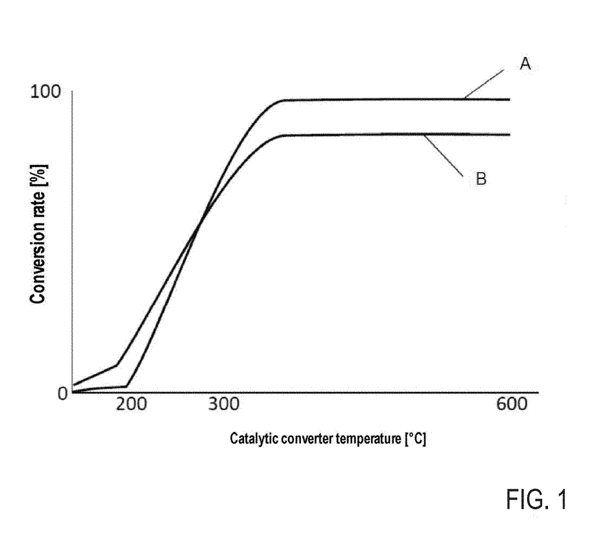
[0082]FIG. 1 shows the dependence of the conversion rate for nitrogen oxides and hydrocarbons (curve A) and carbon monoxide (curve B) on the catalytic converter temperature. It is only at a temperature of approximately 250° C. to 300° C. that the light-off temperature is attained, i.e. the conversion rate is 50%. For an effective catalytic treatment of exhaust gas, the catalytic converter temperature should therefore be above this light-off temperature. The method according to the invention and the exhaust-gas heat management system according to the invention enable this to be achieved for as a long a time period as possible, and thus to reduce the emission of air pollutants.

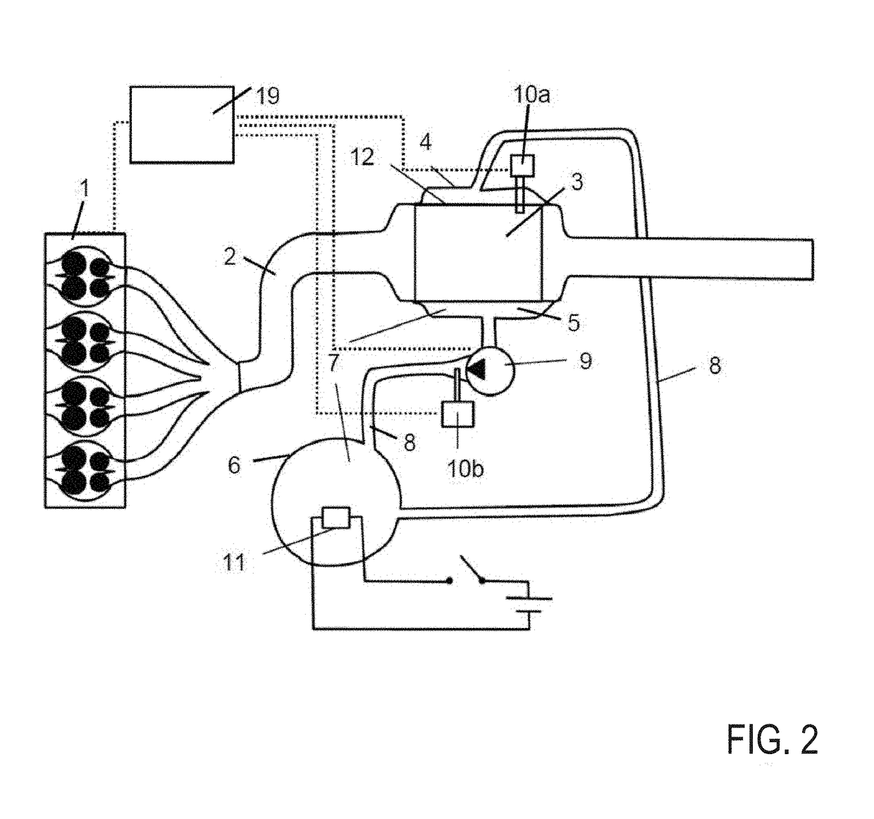
[0083]Shown schematically in FIG. 2 is an exhaust-gas heat management system that may be used, for example, for executing the method according to the invention. The internal combustion engine has an internal combustion engine 1, having an exhaust-gas train 2 adjoining the latter. In the exemplary embodiment, the...


PUM


Abstract

A exhaust-gas heat management system includes a catalytic converter in the exhaust-gas train of an internal-combustion engine, a cover enclosing the catalytic converter, and thereby realizing a cavity for holding a latent-heat storage PCM, at least two fluid connections between the cavity and the collecting vessel, and a pump device for activating and deactivating a PCM circuit between the cavity and the collecting vessel by means of the fluid connections. A method comprises determining an operating state of the internal combustion engine, determining the catalytic converter temperature, determining the PCM temperature, activating the PCM circuit if the PCM temperature is above a phase transition temperature of the PCM, and the internal combustion engine is in a switched-on operating state or the internal combustion engine is in a switched-off operating state and the catalytic converter temperature is below a light-off temperature of the catalytic converter.

Description

CROSS REFERENCE TO RELATED APPLICATION[0001]This application claims priority to German Patent Application No. 102017213213.2, filed Aug. 1, 2017. The entire contents of the above-referenced application are hereby incorporated by reference for all purposes.FIELD[0002]The invention relates to a method for controlling an exhaust-gas heat management system, to an exhaust-gas heat management system, to a motor vehicle having such an exhaust-gas heat management system, and to a computer program product.BACKGROUND AND SUMMARY[0003]Hybrid electric motor vehicles, e.g. so-called plug-in hybrid electric vehicles (PHEV), have a rechargeable battery, and can usually be operated in at least two differing modes.[0004]As long as the charge state of the battery is sufficiently high, the hybrid electric motor vehicle can be operated in a mode that reduces the battery charge state, for example in an exclusively electric driving mode, i.e. using exclusively the electric drive train comprising the batt...

Claims


Application Information

Patent Timeline
Patent Type & Authority Applications(United States)
IPC IPC(8): F01N9/00F01N3/20F01N11/00B01D53/94F01P3/20
CPCF01N9/00F01N3/2006F01N11/002B01D53/9495F01P3/20F01N2900/0416F01N2900/1602F01N2900/08F01P2060/18F01N2900/10F01N2900/12F01N5/02F01N13/141F01N13/16F01N2240/10F01N2260/08F01N2470/08F01N2560/06F01N2560/14F01N2590/11F01N2900/0414F01N2900/102F01N2900/104Y02T10/12Y02T10/40
Inventor ZENNER, THOMASWIRTH, MARTINKAUFMANN, LARSTOEREMIS, MEHMETKOK, DANIEL BENJAMIN
Owner FORD GLOBAL TECH LLC
Why Eureka
Try Eureka