Scraper device for milling drums of a construction machine

a technology of scraper blade and construction machine, which is applied in the direction of cutting machines, constructions, roads, etc., can solve the problems of high amount of effort required to disengage the scraper blade that is jammed in this way, and the scraper blade is difficult to be lowered into the previously milled track by the machine operator,

Active Publication Date: 2008-10-21
WIRTGEN GMBH
View PDF2 Cites 23 Cited by
  • Summary
  • Abstract
  • Description
  • Claims
  • Application Information

AI Technical Summary

Benefits of technology

[0008]The invention provides in an advantageous manner that second centering devices act upon the upper end of the scraper blade, restricting the lateral displacement of the scraper blade at the upper end in case of lateral movement of the scraper blade in the guides.

Problems solved by technology

Previously known centering devices which consist, for example, of cams projecting laterally from the scraper blade, which engage with lateral guides of the scraper blade and restrict the lateral play of the scraper blade in the engagement position of these cams, have not been capable of preventing jamming.
However, if the milling operation has to be interrupted due to, for instance, the replacement of tools, and the milling machine with the milling drum must dive into an existing cut, then it is very difficult for the machine operator to also lower the scraper blade into the previously milled track if the permitted lateral play is too large.
If the scraper blade does not enter the existing milled cut due to the lateral play but hits the still untreated road surface with one side instead, then the scraper blade jams, and a high amount of effort is required to disengage a scraper blade that is jammed in this way.
Milled material then remains in the milled track, in which case there is the additional hazard of persons being injured by milled material that is thrown out through the unclosed opening of the drum housing.

Method used


Image

  • Scraper device for milling drums of a construction machine
  • Scraper device for milling drums of a construction machine
  • Scraper device for milling drums of a construction machine

Examples


Embodiment Construction

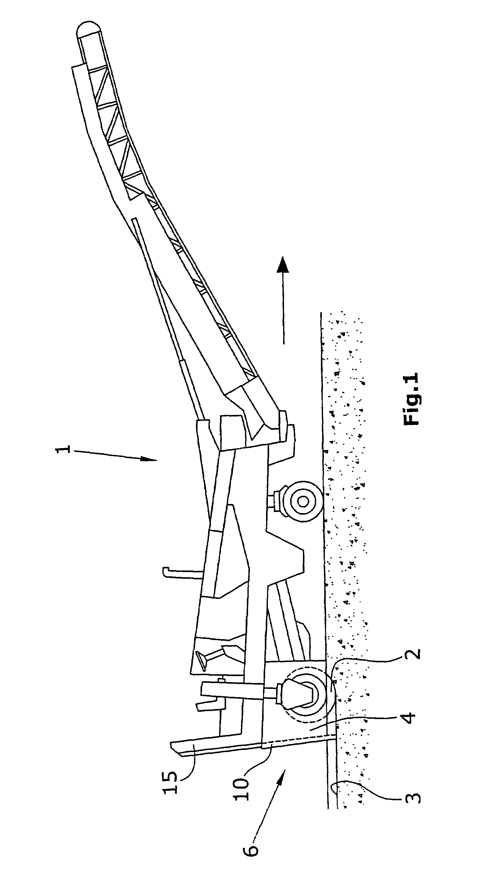
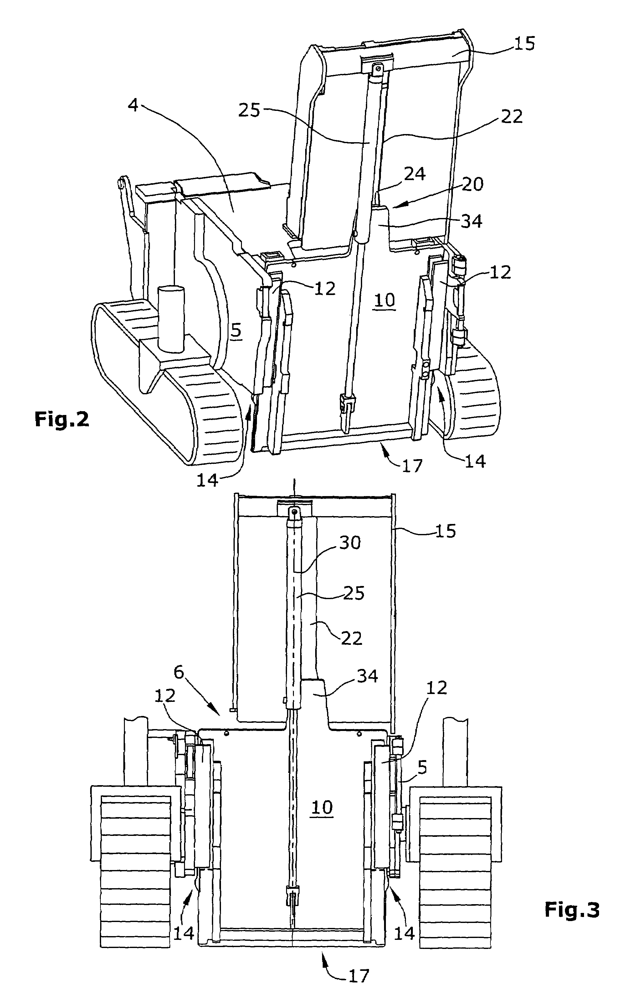
[0037]FIG. 1 shows the use of the invention in a front-loading road milling machine. The automotive road milling machine 1 shown in FIG. 1 is equipped with wheels, but can, of course, also be borne by crawler track units as they are depicted in FIG. 2. In the embodiment of the road milling machine 1 in accordance with FIG. 1, the milling drum 2 is arranged at the rear end of the machine and is enclosed by a drum housing 4.

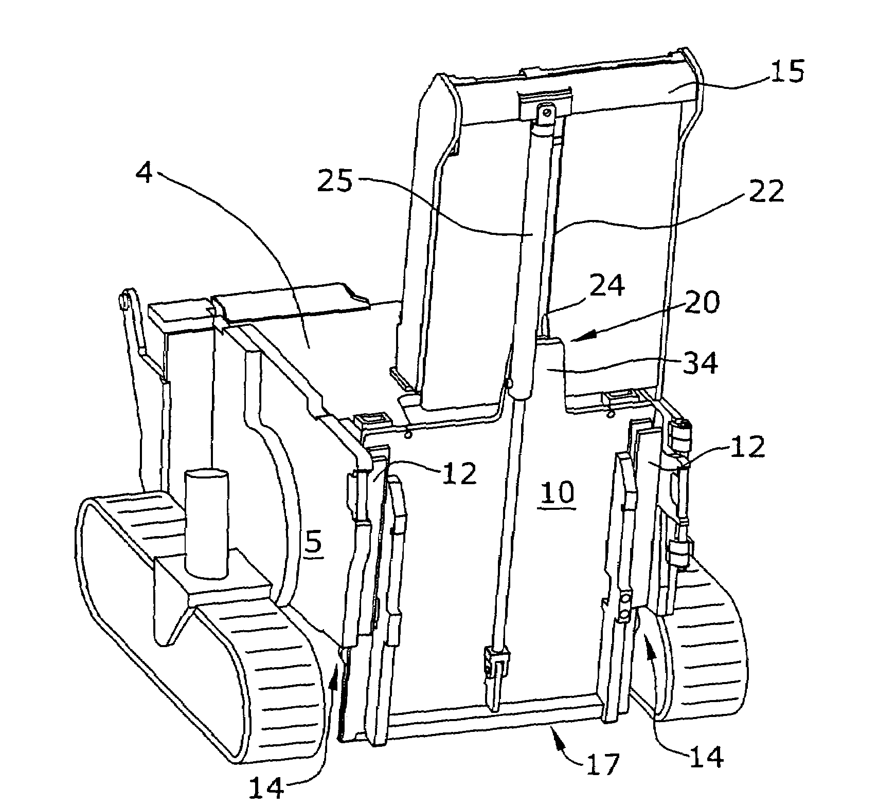
[0038]A scraper device 6 with a portal 15 and a piston cylinder unit 25 is arranged at the rear end of the drum housing 4 when seen in the direction of travel, the said scraper device 6 showing a height-adjustable scraper blade 10 which covers the milling width of the milling drum 2 and is guided in a height-adjustable manner, for example, in the portal 15 attached to the machine frame 5 by means of the piston cylinder unit 25.

[0039]The scraper blade 10 is guided in lateral guides 12 of the machine frame 5, whereby it has to be made clear that the machine element d...


PUM


Abstract

In a scraper device for a milling drum (2) mounted in a construction machine, with a scraper blade (10) arranged in a height-adjustable manner behind the milling drum (2) when seen in the direction of travel, which can glide on the surface (3) milled or to be milled by the milling drum (2), where the scraper blade (10) is guided in lateral guides (12) in a height-adjustable manner relative to the milling drum (2), and where first centering devices (14) are provided which center the scraper blade (10) between the guides (12) with small lateral play of movement when in a raised position, and which allow a greater lateral play of movement of the scraper blade (10) when the scraper blade (10) is in a lowered working position, it is provided that the second centering devices (20) act upon the upper end (16) of the scraper blade (10), restricting the lateral displacement of the scraper blade (10) at the upper end (16) in case of a lateral movement of the scraper blade (10) in the guides (12).

Description

BACKGROUND OF THE INVENTION[0001]The invention relates to a scraper device for a milling drum mounted in a construction machine.[0002]Such a scraper device is known, for instance, from DE 102 47 579.[0003]The scraper device for milling drums of a construction machine described therein, in particular of a road milling machine wherein milling drums of different milling widths can be used within a maximum milling width, consists of a scraper blade that can glide on the surface milled or to be milled by the milling drum.[0004]The scraper blade is required to scrape milled material, which accumulates behind the milling drum when seen in the direction of travel, from the milled surface in order to leave behind a thoroughly clean milled area. When doing so, the material that has accumulated behind the milling drum is fed to the milling drum once again until it is accepted and transported away by a transport device.[0005]Previously known centering devices which consist, for example, of cams...

Claims


Application Information

Patent Timeline
Patent Type & Authority Patents(United States)
IPC IPC(8): E01C23/088
CPCE01C23/088
Inventor BOEHME, HEIKOLEY, HERBERTKURSCHEID, URBANTEWES, GUENTER
Owner WIRTGEN GMBH
Why Eureka
Try Eureka