Memory card connector

a memory card and connector technology, applied in the direction of coupling devices, coupling bases/cases, coupling devices, etc., can solve the problems of unstable the terminals of the memory card connector are crushed and broken, and the memory card connector is not described above. , to achieve the effect of stable signal transmission between the memory card and the memory card connector, simple structure and easy assembly and manufacturing

Inactive Publication Date: 2008-10-21
CHENG UEI PRECISION IND CO LTD
View PDF4 Cites 16 Cited by
  • Summary
  • Abstract
  • Description
  • Claims
  • Application Information

AI Technical Summary

Benefits of technology

[0008]As described above, the anti-mismating portion is designed in accordance with the industry standard of the memory card, which ensures that the memory card is inserted into the card cavity in a correct way. The memory card connector has a simple structure and is easy to be assembled and manufactured. In addition, whether the contacting projection of the switch terminal electrically contacts the touching portion of the metallic shell or not indicates that the memory card is fully inserted into the memory card connector or not, ensuring the signal transmission between the memory card and the memory card connector to be stable.

Problems solved by technology

However, the memory card connector described above has no structure to prevent incorrect insertion therein of the memory card.
Once the memory card is inserted into the memory card connector in a wrong way, the terminals of the memory card connector are crushed and broken.
Therefore, the connection between the memory card and the memory card connector is susceptible to being interrupted, resulting in unstable signal transmission between the memory card and the memory card connector.

Method used


Image

  • Memory card connector
  • Memory card connector
  • Memory card connector

Examples


Embodiment Construction

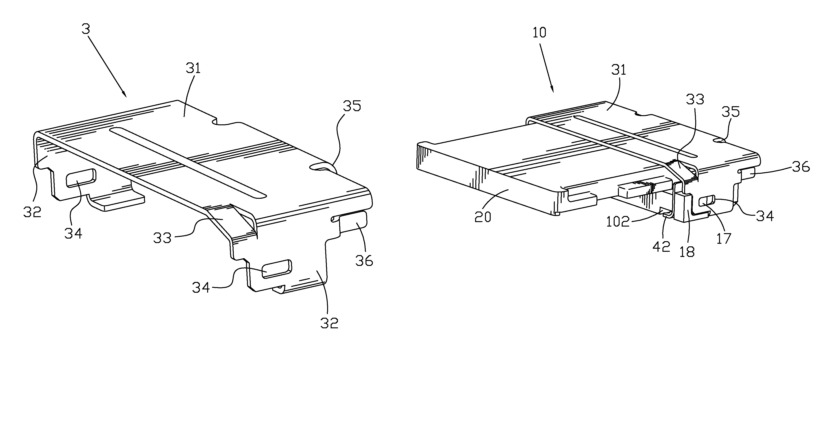
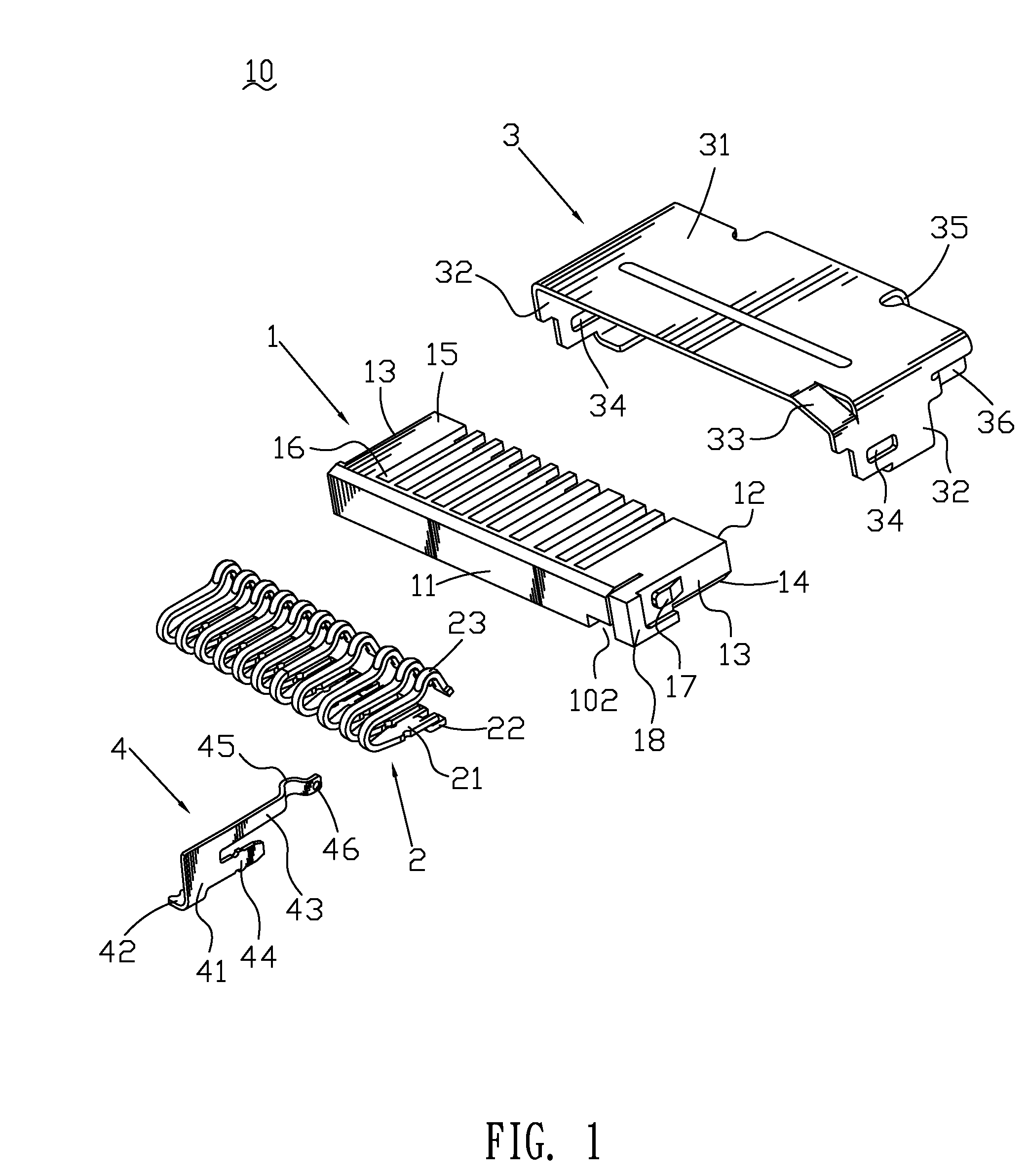
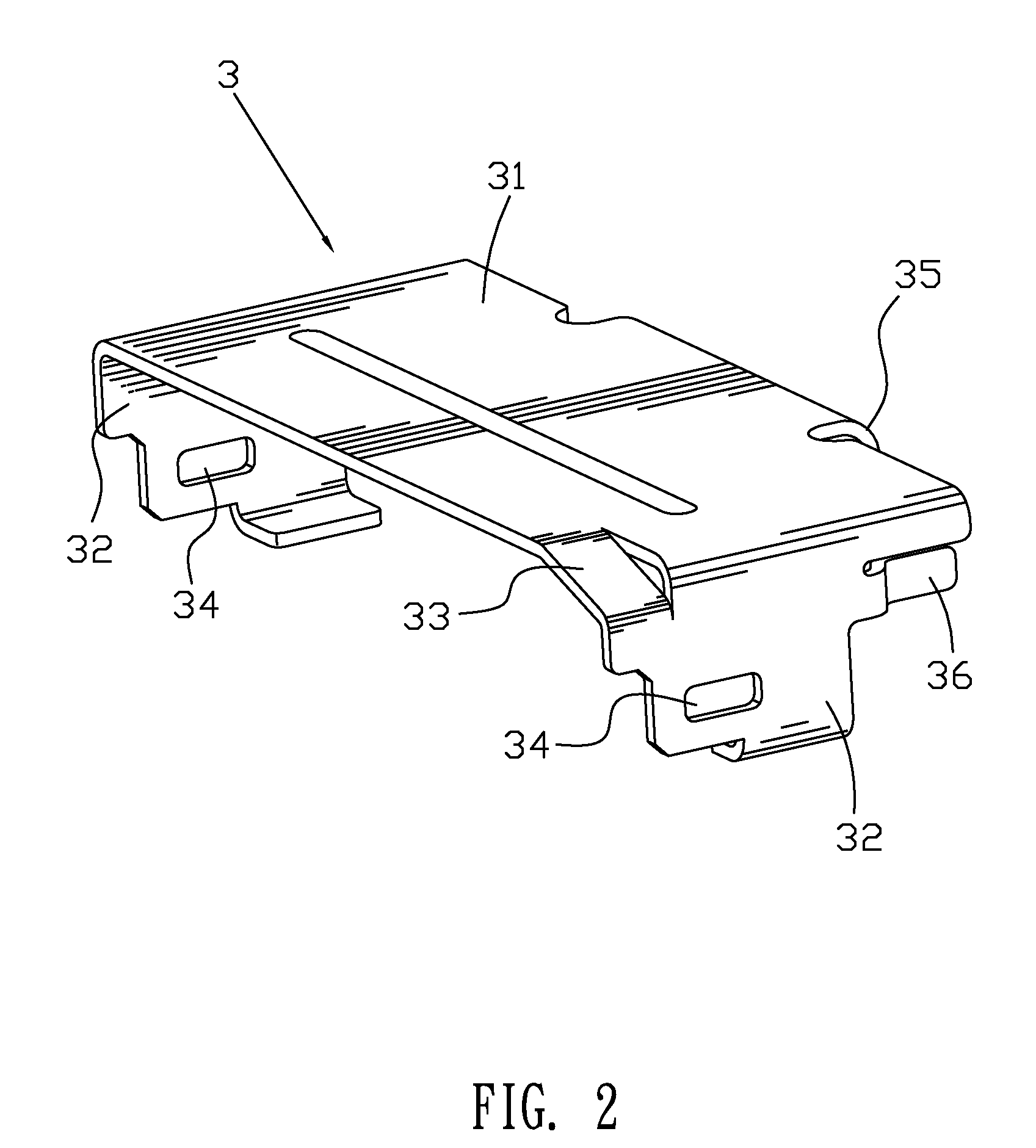
[0015]Referring to FIG. 1 and FIG. 3, a memory card connector 10 mountable on a printed circuit board (not shown) and electrically connecting with a memory card (shown in FIG. 5) includes an insulating housing 1, a plurality of conductive terminals 2 received in the insulating housing 1 respectively, a metallic shell 3 coupling with the insulating housing 1 to form a card cavity 101 therebetween for receiving the memory card therein, and a switch terminal 4 received in the insulating housing 1. In a preferred embodiment of the present invention, the memory card is a Memory Stick Micro Card 20 which will be called M2 card for short in the following description.

[0016]Please refer to FIG. 1. The insulating housing 1 is substantially rectangular and disposed transversely. The insulating housing 1 has a front wall 11, a rear wall 12, two sidewalls 13, a bottom wall 14 and a top wall 15. The insulating housing 1 longitudinally defines a plurality of conductive terminal grooves 16 in a sid...


PUM


Abstract

A memory card connector includes an insulating housing defining conductive terminal grooves and a switch terminal groove. A metallic shell coupling with the insulating housing to form a card cavity therebetween has a top section and two side sections. The front of a top surface of one side section extends and inclines to the front of the top section to form an anti-mismating portion connecting with the front of the top section to form an inclined corner at the front of the metallic shell. One side section extends rearward to form a touching portion protruding toward the inner of the card cavity. Conductive terminals received in the conductive terminal grooves have a base portion, a soldering portion and a contacting portion. A switch terminal assembled in the switch terminal groove has a main body extending rearward to form a resilient arm received in the card cavity. The resilient arm defines a contacting projection facing the touching portion and a pressing portion facing the inner of the card cavity.

Description

BACKGROUND OF THE INVENTION[0001]1. Field of the Invention[0002]The present invention relates generally to a memory card connector, and more particularly to a memory card connector having an anti-mismating portion to prevent incorrect insertion of a memory card.[0003]2. The Related Art[0004]Recently, electronic devices, such as digital cameras, MP3 players, cellular phones, etc., are required with larger capacity of storage to store data. A memory card, such as a Memory Stick Duo card, a SD card, a Mini SD card, a MMC card, a M2 card, etc., which has larger capacity of storage and a small size, is extensively used to expend the capacity of storage of the electronic devices. The data transmission between the electronic device and the memory card is through a memory card connector mounted on a PCB (printed circuit board) of the electronic device for connecting with the memory card. The memory card connector has an insulating housing. The insulating housing includes a receiving cavity ...

Claims


Application Information

Patent Timeline
Patent Type & Authority Patents(United States)
IPC IPC(8): H01R24/00
CPCH01R13/7035H01R12/7094H01R13/506H01R23/6873H01R13/658
Inventor HUNG, PEI-CHIAOYANG, MEI-CHUAN
Owner CHENG UEI PRECISION IND CO LTD
Why Eureka
Try Eureka