Method and device for fastening and aligning a sensor

a sensor and fastening technology, applied in the direction of photometry using electric radiation detectors, optical radiation measurement, instruments, etc., can solve the problems of time and cost saving, deviation of the sensor axis from the nominal direction, and inability to precisely align the sensor. achieve the effect of increasing the useful range of the stereo camera system

Inactive Publication Date: 2008-10-21
ROBERT BOSCH GMBH
View PDF14 Cites 49 Cited by
  • Summary
  • Abstract
  • Description
  • Claims
  • Application Information

AI Technical Summary

Benefits of technology

[0007]The method described below, for fastening and aligning a sensor via a holding element to a support, may provide that a precise alignment of the sensor axis takes place in the nominal direction. In motor vehicles, stereo camera systems are used, for example, to gather information from the surroundings of the motor vehicle, the stereo camera systems being made up of two video sensors, which record essentially the same scene. To evaluate the image information, two overlapping image ranges of the two video sensors may be required. The viewing angle of the two video sensors recorded in common defines, in this case, the range of the stereo camera system. Because of the precise alignment of the video sensors, the method described herein may increase the useful range of the stereo camera system. In the case of stereo camera systems, the method described and the device may make possible the fastening and the precise alignment of the sensor axes of the two video sensors relative to each other. For example, the setting of the sensor axes of the two video sensors is made possible such that there is squinting or strabismus of the video sensors. In this context, the recorded range of the stereo camera system is placed closer to the motor vehicle during installation in the motor vehicle.
[0008]By reworking the sensor seating surface, the method described in the following and the device may make possible the fastening and alignment of at least one sensor, e.g., in motor vehicles. The precise alignment of the sensor axis of the at least one sensor may be achieved by the determination using measuring techniques of the deviation of the sensor axis from the nominal direction by the surveying of the sensor seating surface and the subsequent reworking.

Problems solved by technology

A disadvantage of these methods is that no precise mechanical alignment of the sensors is undertaken.
The holding element often also has component part tolerances, which result in deviation of the sensor axis from the nominal direction.
When the method described is used for fastening video sensors to the inside of the windshield of a motor vehicle, the method described may lead to time and cost saving, because the two method steps may be carried out in parallel.
This may lead to an extension of the useful life of the sensors, since otherwise, for example, remaining diluted soluble oil or cutting oil may be able to lead to corrosion of the sensor and / or the holding element.
This may lead to an execution of the method that saves time and costs, since an additional processing of the holding element may not be necessary.
This may make reworking the sensor's antechamber, while processing the sensor seating surface, unnecessary.
This may lead to an execution of the method described that saves time and costs.

Method used


Image

  • Method and device for fastening and aligning a sensor
  • Method and device for fastening and aligning a sensor
  • Method and device for fastening and aligning a sensor

Examples


Embodiment Construction

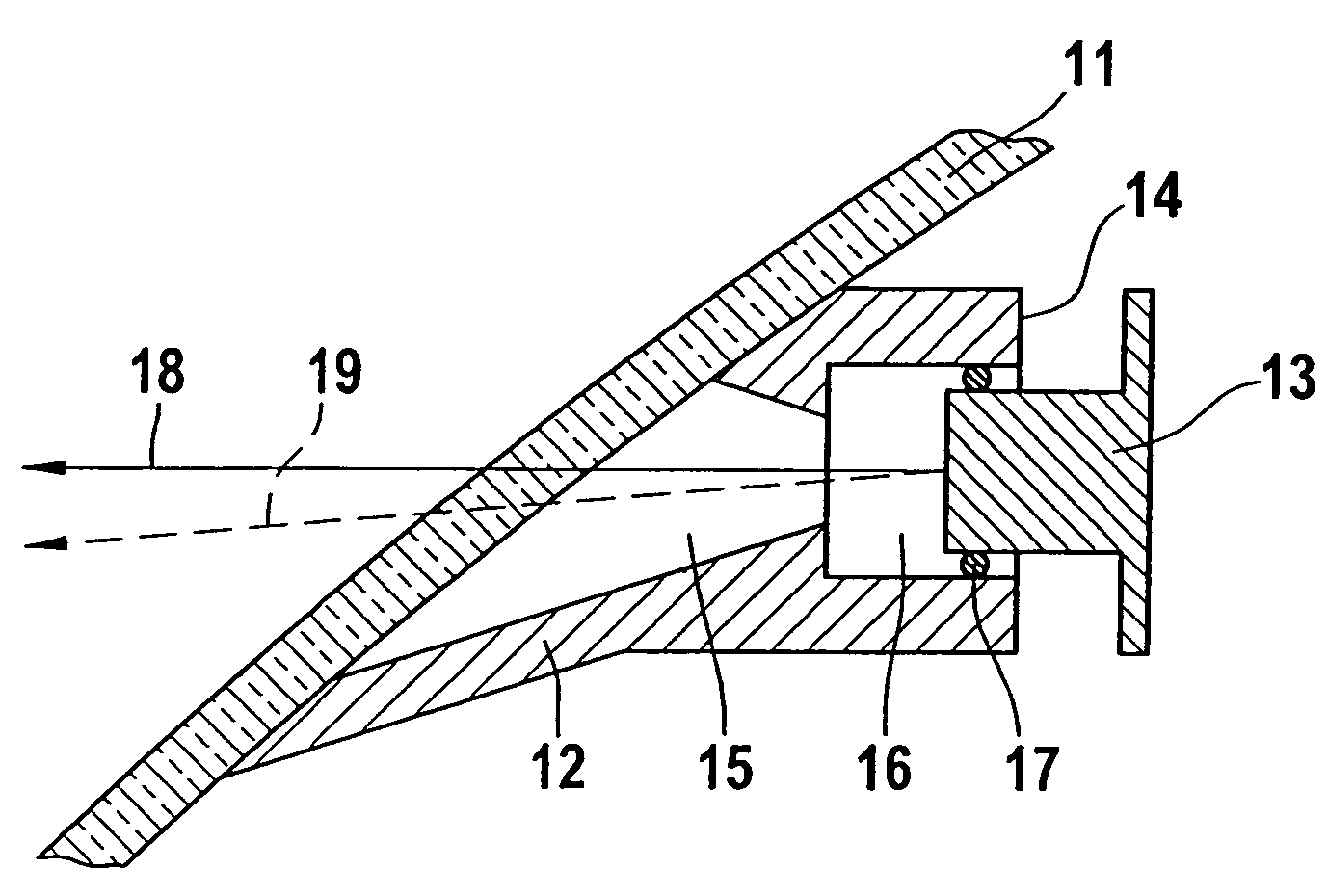
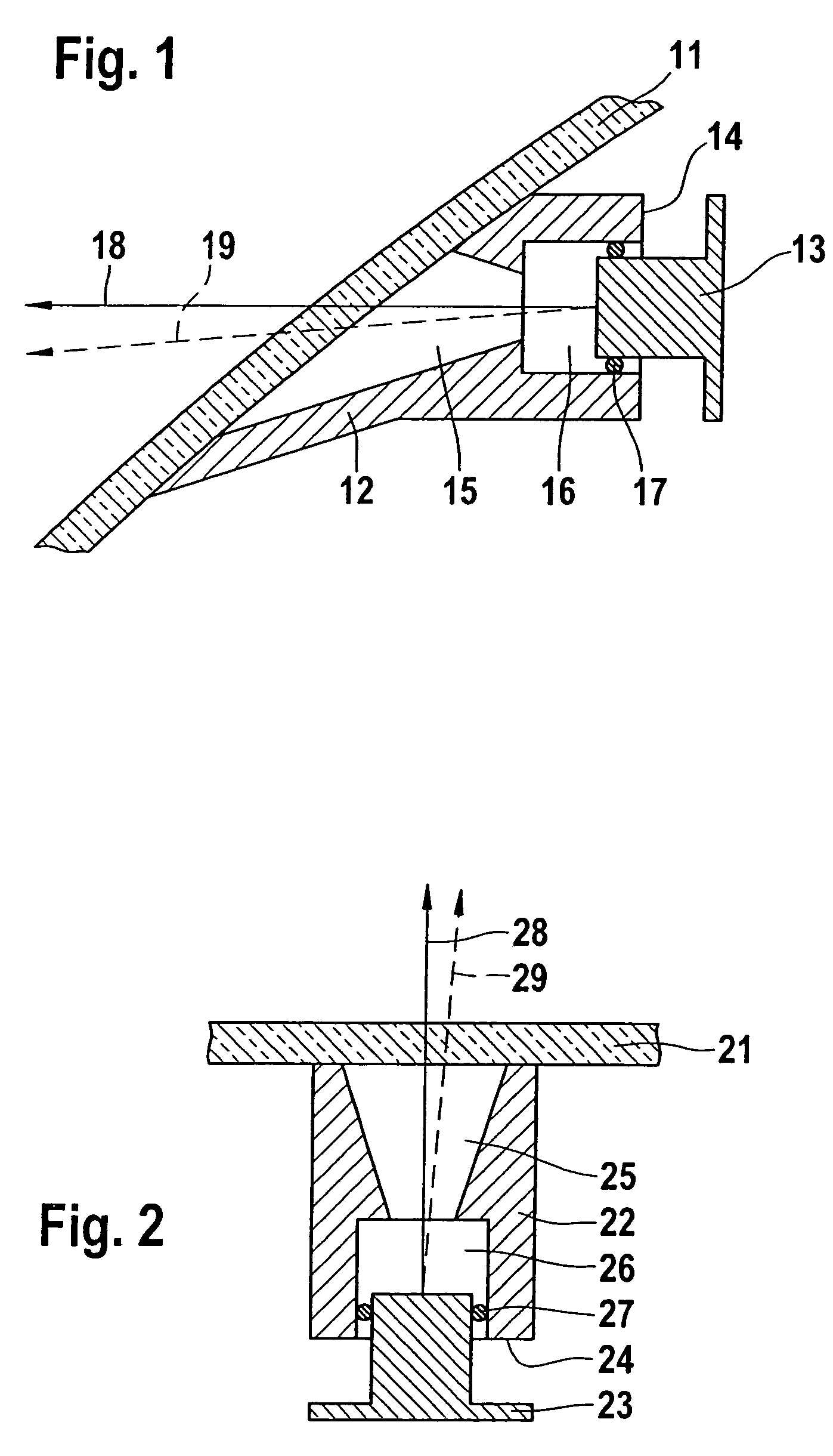
[0029]FIGS. 1 and 2 show the side view and the top view of a device for fastening and aligning a sensor 13, 23, in an exemplary embodiment a video sensor, before the reworking of sensor seating surface 14, 24. The support 11, 21, on which video sensor 13, 23 is mounted, is the windshield of a motor vehicle. Video sensor 13, 23 is connected via a holding element 12, 22 to the support 11, 21. The connection of video sensor 13, 23 to holding element 12, 22 is made via seating surface 14, 24. Holding element 12, 22, in an exemplary embodiment, has a cylindrical accommodation 16, 26 for a part of video sensor 13, 23. Sensor antechamber 15, 25 is used as a baffle, for the reduction of interfering, stray pick-up light. In FIGS. 1 and 2, the deviation of sensor axis 18, 28 from the nominal direction 19, 29 is illustrated. In an exemplary embodiment, sensor axis 18, 28 is determined by the optical axis of the video sensor 13, 23. In an exemplary embodiment, nominal direction 19, 29 is determ...


PUM

PropertyMeasurementUnit
adhesionaaaaaaaaaa
distanceaaaaaaaaaa
mechanical alignmentaaaaaaaaaa

Abstract

A method and a device are provided for fastening and aligning a sensor, e.g., in motor vehicles, the sensor being connected to a support via a holding element. By reworking the sensor seating surface, a precise alignment of the sensor axis with the nominal direction may be achieved.

Description

[0001]This application is a national stage entry of PCT / DE03 / 02314, filed on Jul. 10, 2003.FIELD OF THE INVENTION[0002]The present invention relates to a method and a device for fastening and aligning a sensor, e.g., a video sensor, on the windshield of a motor vehicle.BACKGROUND INFORMATION[0003]Motor vehicles may be equipped with a plurality of sensors, such as ultrasound sensors or video sensors, in order, for example, to gather information about the surroundings of the motor vehicle. The fastening and aligning of these sensors on the vehicle deserve great importance, in this context, so that the functioning of the sensors may be ensured.[0004]In particular, in motor vehicles, video sensors are used in larger numbers for gathering information on the surroundings. Stereo camera systems, for instance, are used for observing the road space located ahead of the motor vehicle, for object recognition or the measurement of distance from a preceding motor vehicle. In this context, in ste...

Claims


Application Information

Patent Timeline
Patent Type & Authority Patents(United States)
IPC IPC(8): B32B41/00B60R11/00B60R11/02B60R11/04
CPCB60R11/04B60R2011/0026B60R2011/0063
Inventor KURFISS, FRANKAPEL, UWESKUPPIN, ANDRE
Owner ROBERT BOSCH GMBH
Why Eureka
Try Eureka