Liquid handling tool having porous plunger

a technology of liquid handling and plunger, which is applied in the direction of volume metering, laboratory glassware, instruments, etc., can solve the problem that the plunger may not create suction/pressure, and achieve the effect of reducing the number of control signals

Inactive Publication Date: 2008-10-21
PROTEDYNE
View PDF63 Cites 57 Cited by
  • Summary
  • Abstract
  • Description
  • Claims
  • Application Information

AI Technical Summary

Benefits of technology

[0008]In another aspect of the invention, individual passageways in plungers may be addressed using a matrix of membrane valves. The valve

Problems solved by technology

However, for plungers that have their passageway open, the plunger

Method used


Image

  • Liquid handling tool having porous plunger
  • Liquid handling tool having porous plunger
  • Liquid handling tool having porous plunger

Examples


Embodiment Construction

[0017]Various aspects of the invention are described below with reference to illustrative embodiments. However, it should be understood that the invention is not limited to those embodiments described below, but instead may be used in any suitable system or arrangement.

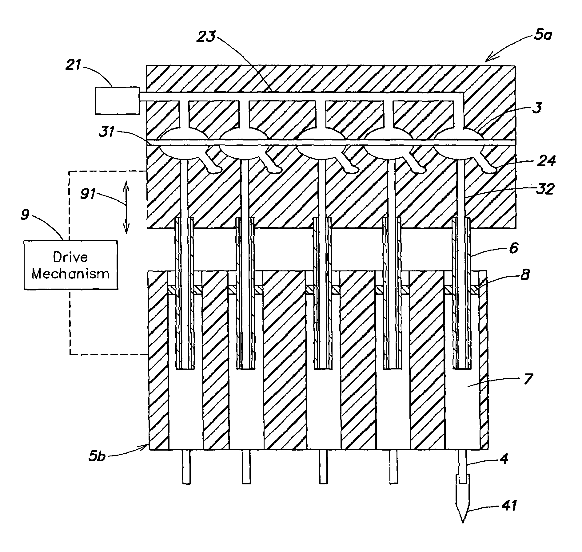
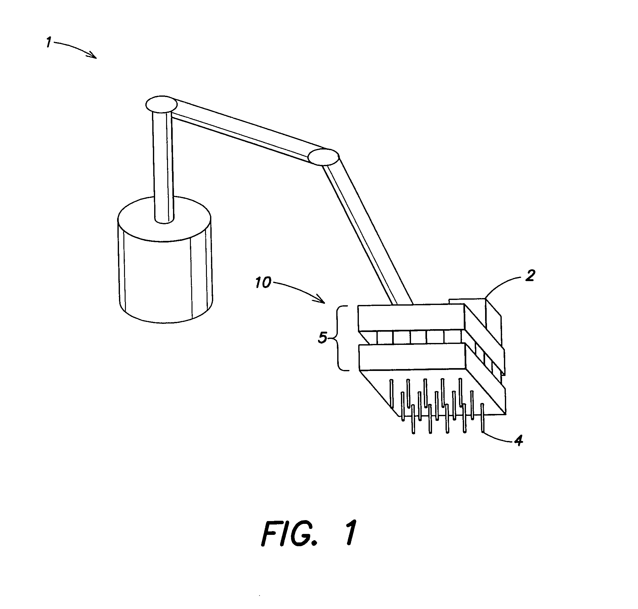
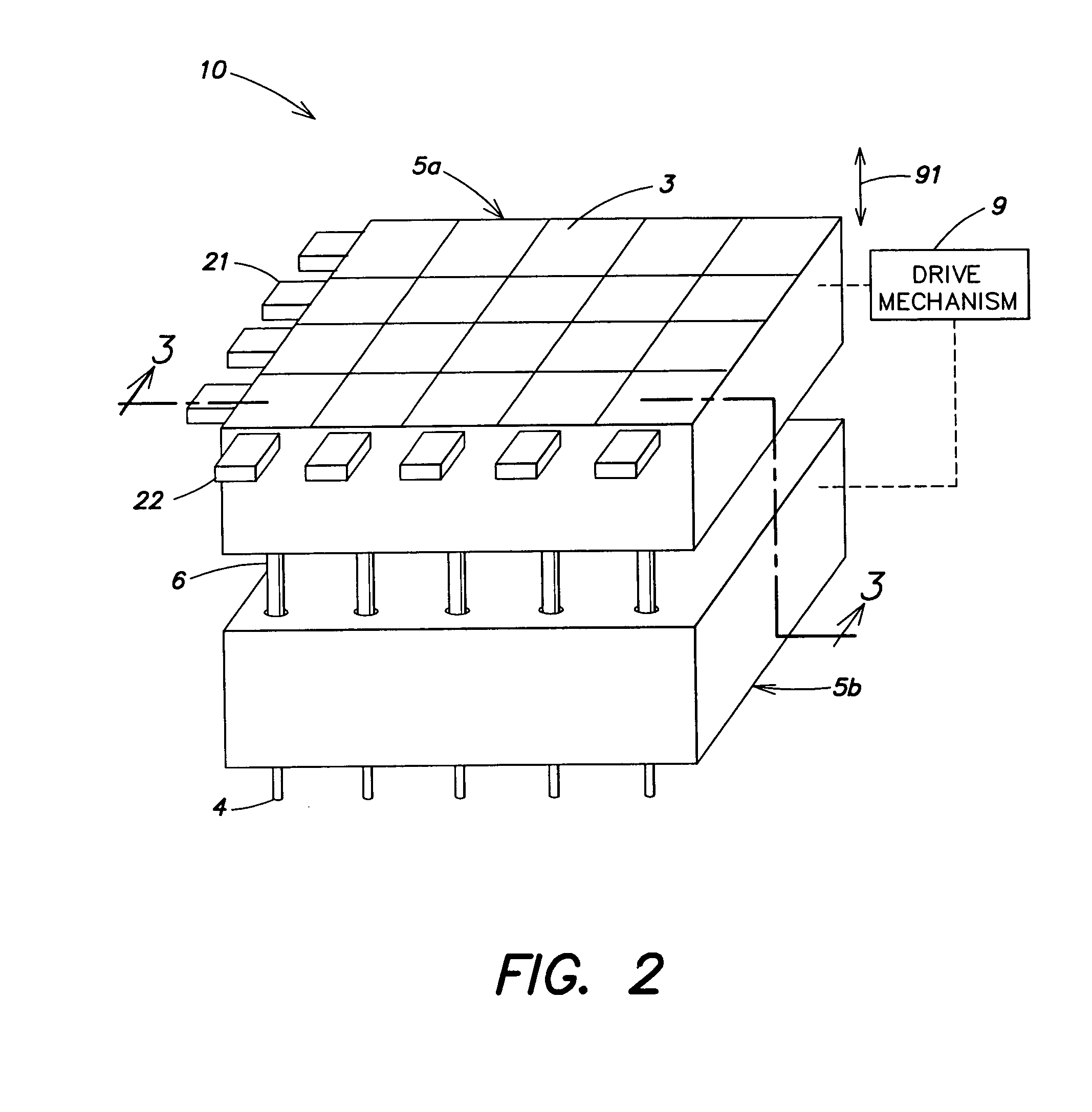
[0018]In one aspect of the invention, plungers in a sample handling tool may have a passageway that can be selectively opened or closed. Selective opening or closing of the passageway may allow a needle associated with each plunger to be selectively actuated. Such actuation may include moving a needle relative to the tool, such as extending the needle away from the tool apart from other needles on the body, controlling flow in the needle, such as drawing fluid into or expelling fluid out from the needle, or otherwise causing the needle to perform one or more material handling functions. In addition, the tool controller may simultaneously actuate all needles in the array, or simultaneously actuate selected groups of ne...


PUM


Abstract

A robotically manipulable sample handling tool, such as a colony picking head or robotic pipetting tool, includes needles arranged on the tool. Actuators are associated with each needle to control flow for the needle. A plurality of plungers are each associated with a needle, and movement of the plungers can actuate a corresponding needle. Each of the plungers has a passageway that may be opened or closed, e.g., to move the corresponding needle and/or draw fluid into/expel fluid from the needle when the plunger is moved in the tool body. The actuators are arranged so that plunger passageways may be individually controlled by a controller.

Description

RELATED APPLICATIONS[0001]This application claims priority to U.S. provisional application Ser. No. 60 / 397,989, filed Jul. 23, 2002.BACKGROUND OF THE INVENTION[0002]1. Field of Invention[0003]This invention relates to sample handling tools, such as robotically manipulated pipetting devices.[0004]2. Related Art[0005]Robotically manipulated tools having a plurality of sample handling needles are widely used, for example, in proteomic and genomic research. These devices are used to move material samples both to and from a variety of different work areas, such as microtiter trays, gels having separated DNA fragments, and other material holding devices. Some such tools may have a plurality of needles arranged in an array that corresponds to wells in a microtiter tray, such as the commonly-known 96-well or 384-well plate. The array of needles arranged to correspond with all of the wells in a microtiter tray may allow material to be simultaneously deposited in, and removed from, wells in t...

Claims


Application Information

Patent Timeline
IPC IPC(8): B01L3/02C40B60/14G01N1/00G01N35/10
CPCB01L3/022G01N35/1074B01L3/0217B01J2219/00364Y10T436/2575B01L2300/049B01L2300/0829B01L2300/123B01L2400/0418B01L2400/0481B01L2400/0655B01L2400/0694C40B60/14G01N35/1072G01N35/109
Inventor MASSARO, PETER
Owner PROTEDYNE
Why Eureka
Try Eureka