Eureka AIR delivers breakthrough ideas for toughest innovation challenges, trusted by R&D personnel around the world.

Method and apparatus for designing, rendering and programming a user interface

Inactive Publication Date: 2008-10-21
CONCEPTS EGERIA
View PDF29 Cites 66 Cited by
  • Summary
  • Abstract
  • Description
  • Claims
  • Application Information

AI Technical Summary

Benefits of technology

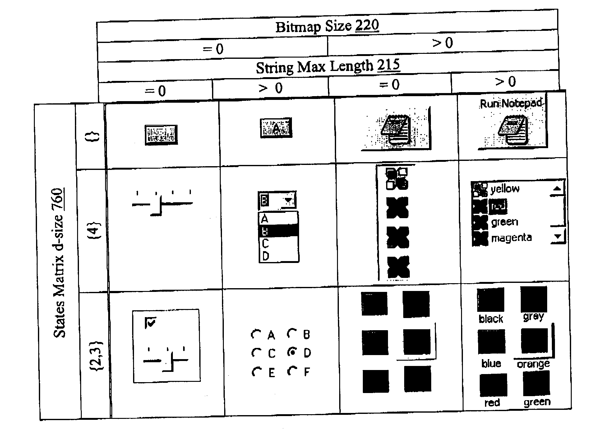
[0013]It will be appreciated that this may provide one solution that can support all devices whatever their differences are in memory size, networking and / or user interface capabilities. Users interfaces are not designed using specific components for specific target platforms; they are designed using three generic conceptual user interface components.
[0015]This methodology mitigates the problem of incompatibilities between the user interfaces of different platforms and also provides a new way of designing a user interface without having to think of where it will be deployed. The generic aspect and natural portability of the conceptual user interface generates a substantial relief for the software developers who are not obliged to understand the capabilities of the different platforms or devices. Instead, they may focus more on designing and defining the functionalities of the application than on accommodating it to run on specific platforms.
[0016]According to its conceptual nature, this invention mitigates the user interface incompatibilities for the existing platforms and devices and will accommodate future platforms or devices.

Problems solved by technology

In smaller devices such as a cellular telephone, a personal digital assistant (PDA) or pager, the display is much smaller and the input device more limited.
Devices such as a PDA may still provide menus and windows to a certain extent, although the limited size inhibits them from using multiple windows.
For each of these platforms, a hierarchy of proprietary components is used, creating an incompatibility between each other.
Moreover, they have inherent limitations: remote access is not available without external software and there is no multi-user collaboration functionality implemented.
Naturally, this results in additional work for each device which is supported.
Furthermore, it is difficult to support new or future devices if their capabilities are not yet known.
This view is usually not suitable for different types of devices.
It also doesn't really run remotely since applets must be downloaded first before running locally on the client.
None of the existing user interface components is really portable on different platforms creating a necessity of redesigning and recoding to support other existing platforms.
Consumer devices have substantial differences in memory size, networking, and user interface capabilities, making it very difficult to support all devices with just one solution.”

Method used


Image

  • Method and apparatus for designing, rendering and programming a user interface
  • Method and apparatus for designing, rendering and programming a user interface
  • Method and apparatus for designing, rendering and programming a user interface

Examples


Embodiment Construction

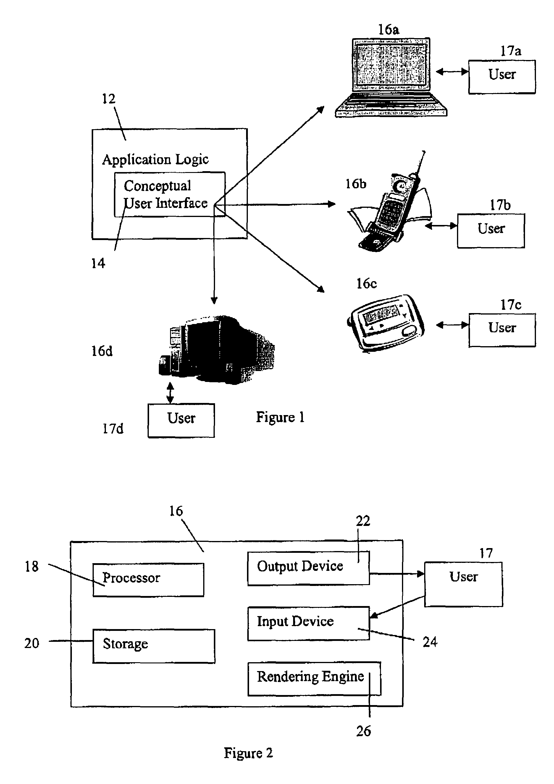
[0081]Referring to FIG. 1, an application environment is shown generally by the numeral 10. In this example, an application 12 incorporates a user interface 14. Users of various devices 16a, 16b, 16c, and 16d are used to run the application 12. The devices may be connected to the application 12 through a network, or alternations may be directly connected thereto. The application 12 may be incorporated into the devices 16. The users interact with the application 12 through the interface 14. The devices 16a, 16b, 16c, and 16d may include stand alone computers, laptops, cellular telephones, pagers, and the like. Each of these devices has different capabilities in its interface.

[0082]Referring to FIG. 2, a sample device is shown by the numeral 16. The device includes a processor 18, the storage 20, an output device 22, a rendering engine 26, and an input device 24. It will be appreciated that the form of these components differs for each device. Some devices may have faster and larger p...


PUM


Abstract

A method of displaying a user interface, comprising the steps of first obtaining a representation of the user interface. The representation includes conceptual components representing multi-dimensional arrays of elements of the user interface. The conceptual components include a vector parameter related to a multi-dimensional size of the array, and matrices having dimensions related to those of the array.The method proceeds by executing a device-specific rendering algorithm on the representation of the user interface and displaying the user interface on the device.

Description

[0001]This application claims the benefit of U.S. Provisional Application No. 60 / 384,375 filed May 30, 2002, Canadian Application No. 2,369,854 filed May 30, 2002, and Canadian Application No. 2,388,101 filed Feb. 1, 2002, the contents of each of which are hereby incorporated by reference.BACKGROUND OF THE INVENTION[0002]1. Field of the Invention[0003]The present invention relates to a method and apparatus for designing, rendering and programming a user interface.[0004]2. Description of the Prior Art[0005]Computer programs interact with their users through user interfaces, which translate user actions into input for the computer and present information to the user in human readable form. Such interfaces are usually designed to be easy to use. Each hardware device which runs the computer program may use a different interface. For example, Windows-based machines use a graphical user interface (GUI) which uses windows, menus and dialog boxes. These interfaces tend to show a lot of info...

Claims


Application Information

Patent Timeline
IPC IPC(8): G06F3/00G06F17/00G06F9/00G06F3/0481
CPCG06F3/0481
Inventor SAVAGE, MARTIN
Owner CONCEPTS EGERIA
Why Eureka
Eureka Blog
Learn More