Optical sensor use in alternate path gravel packing with integral zonal isolation

a technology of optical sensors and zone isolation, applied in the direction of sealing/packing, borehole/well accessories, survey, etc., can solve the problems of undesirable fluid entry into longitudinal passages, inability to provide any means for radial communication of fluid outwardly, and easy collapse of open-hole systems along their uncased portions. , to achieve the effect of facilitating post-deployment fiber optic installation

Active Publication Date: 2008-10-28
BAKER HUGHES HLDG LLC
View PDF20 Cites 62 Cited by
  • Summary
  • Abstract
  • Description
  • Claims
  • Application Information

AI Technical Summary

Benefits of technology

[0012]The invention provides devices and methods for monitoring wellbore conditions while conducting hydrocarbon production within a wellbore, particularly an open-hole wellbore, having multiple zones within. In a currently preferred embodiment, a production tubing string assembly is made up having a plurality of packers suitable for sealing within an open-hole wellbore having multiple individual zones. The packers are preferably set using hydraulic fluid pressure present within the flowbore of the production tubing string. In addition to the packers, the production tubing string includes production nipples having perforated screens for removal of debris from produced fluids. One or more fiber optic sensor lines are disposed upon the outside of the screens and running portion of the production tubing string. Alternatively, hydraulic control lines are disposed upon the outside of the screen to facilitate post-deployment fiber optic installation. The sensor line or lines are disposed through the packers using a pass-through system so as to provide unbroken sensing line(s) to the surface of the wellbore. This allows temperature, pressure or other wellbore conditions to be monitored at the surface in each of the individual zones of interest.

Problems solved by technology

Open-hole systems are prone to collapse along their uncased portions.
Unfortunately, conventional large expansion packer systems generally lack the ability to pass electrical or fiber optic cables or fluid conduits axially through the packer assembly so that other devices may be used below the packer device.
The potential exists for improper sealing between the carrier and mandrel during fabrication of the tool, leading to undesirable fluid entry into the longitudinal passages.
Additionally, this design does not offer any means for radial communication of fluid outwardly from the flowbore of the tool to the radial exterior of the tool.
If the carrier and mandrel of this tool were perforated to allow radial fluid communication, the passages defined therebetween would undesirably become exposed to external wellbore fluid pressures.
To the inventor's knowledge, conduit feed through systems have not been successfully integrated into hydrostatically-set packer assemblies.
It is believed that this failure is due to the complexity of a hydrostatic setting mechanism and the need for such a device to communicate hydrostatic fluid pressure through the inner mandrel of the packer assembly and into a chamber within the exterior portion of the packer assembly.
The use of multiple interior pieces, such as a separate carrier and mandrel, to define a longitudinal cable / conduit pass-through, and the attendant assembly requirements, also adds to the difficulty of incorporating a cable feed-through feature into a hydrostatically-set device.
A further problem with the use of conventional production assemblies in open-hole, multi-zonal wellbores is that it is difficult to monitor the temperature and pressure of the separate zones.
Thus, temperature, pressure or other conditions within a particular zone cannot be monitored within the annulus.
This makes controlled production from individual zones much more difficult.
However, this system lacks any means for monitoring temperature, pressure or other conditions within the individual zones.
In addition, the system lacks any means for communication of power or data across the isolators within the annulus.

Method used


Image

  • Optical sensor use in alternate path gravel packing with integral zonal isolation
  • Optical sensor use in alternate path gravel packing with integral zonal isolation
  • Optical sensor use in alternate path gravel packing with integral zonal isolation

Examples


Embodiment Construction

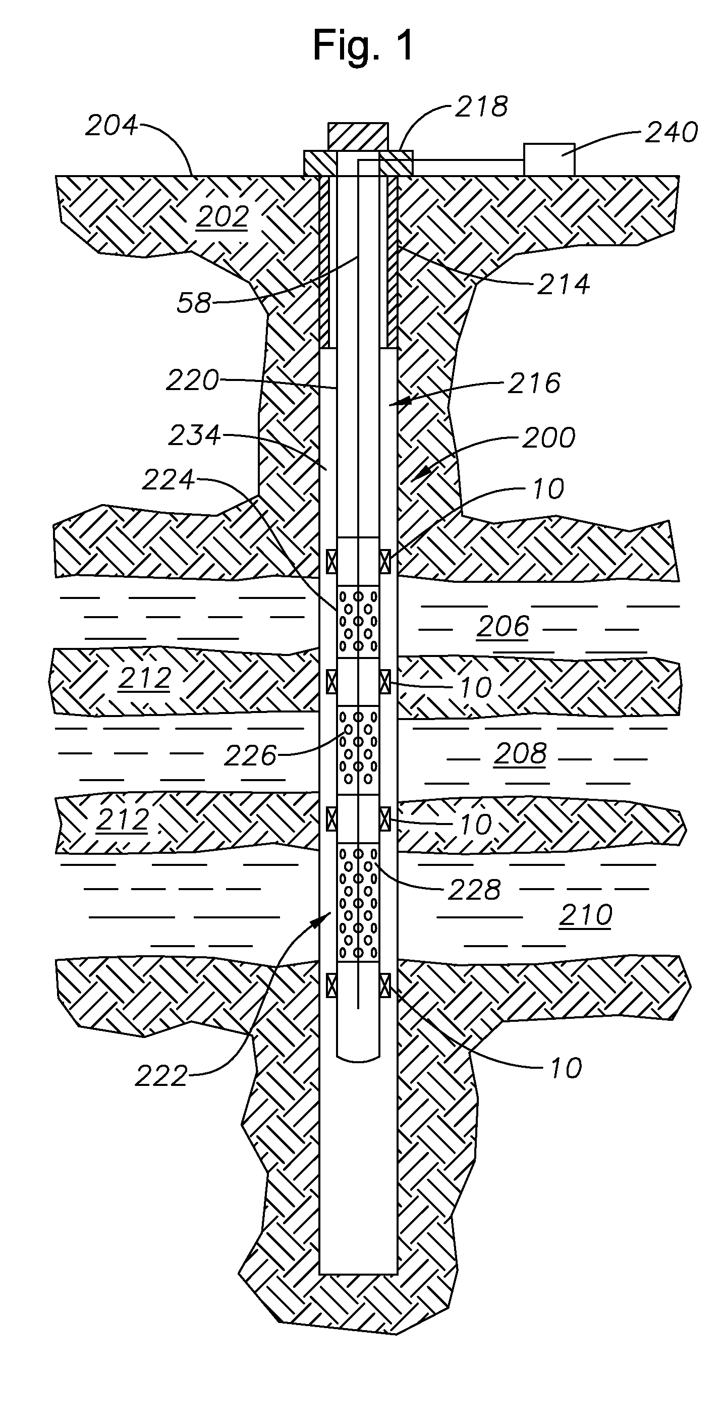
[0023]FIG. 1 illustrates an exemplary open-hole wellbore 200 that has been drilled through the earth 202 from the surface 204. Although the wellbore 200 is depicted as being substantially vertically-disposed along its length, those of skill in the art will understand that portions of the wellbore 200 may be deviated or even horizontally-disposed. The wellbore 200 extends through a number of individual fluid-bearing zones 206, 208, 210 that are separated from one another by substantially impervious layers 212 of rock. In this example, each of the zones 206, 208, 210 contain oil or gas to be produced. A section of casing 214 is cemented into place near the surface 204 of the wellbore 200. However, those portions below the casing section 214 are open-hole portions that are not lined with casing.

[0024]Production tubing string assembly 216 is shown disposed within the wellbore 200 and suspended from a tubing hanger 218 at the surface 204. It is noted that fluid valving and other surface-...


PUM


Abstract

Devices and methods for monitoring wellbore conditions while conducting hydrocarbon production within a wellbore, particularly an open-hole wellbore, having multiple zones within. A production tubing string assembly is made up having a plurality of packers for sealing within an open-hole wellbore having multiple individual zones. The production tubing string includes production nipples and one or more fiber optic sensor lines disposed upon the outside of the production tubing string. The sensor line or lines are disposed through the packers using a pass-through system so as to provide unbroken sensing line(s) to the surface of the wellbore. This allows temperature, pressure or other wellbore conditions to be monitored at the surface in each of the individual zones of interest.

Description

[0001]This application is a continuation-in-part to U.S. patent application Ser. No. 11 / 180,150 filed Jul. 13, 2005 now abandoned.BACKGROUND OF THE INVENTION[0002]1. Field of the Invention[0003]The invention relates generally to systems and methods for production from open-hole wellbores having multiple zones within. In more particular aspects, the invention relates to production systems that are useful for gravel packing and isolating separate zones within an open-hole wellbore and which allow monitoring of wellbore conditions within the separate zones.[0004]2. Description of the Related Art[0005]Hydrocarbon production wellbores often extend through a number of separate zones within the earth. These zones are separated by layers of relatively impermeable rock. The individual zones may contain oil, gas, water, or a mixture of these fluids. It is desirable to isolate the individual zones within the wellbore to prevent movement of fluids between the zones within the wellbore, which co...

Claims


Application Information

Patent Timeline
Patent Type & Authority Patents(United States)
IPC IPC(8): E21B43/14E21B33/12E21B47/06E21B47/12
CPCE21B17/025E21B17/1035E21B17/18E21B33/1285E21B47/06E21B47/123E21B47/135
Inventor CORONADO, MARTIN P.PETERSON, ELMER R.
Owner BAKER HUGHES HLDG LLC
Why Eureka
Try Eureka